Project: HiCAD Steel Engineering
"Civil Engineering functions" docking window > Steel Engineering > General > Stiffener (2401)
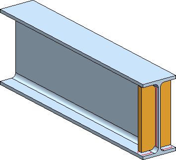
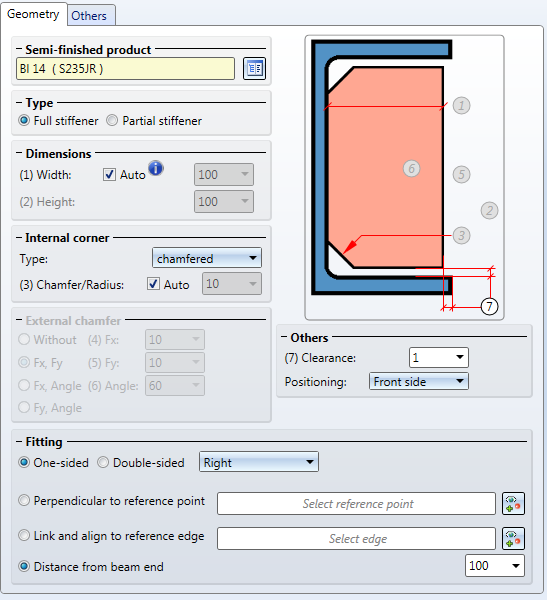
Use this Design Variant to fit one-sided or double-sided stiffeners with filleted or chamfered (inner or outer) corners.
Identify the beam at the end where you want to attach the stiffener. The Stiffener dialogue window will then be displayed.
Click Preview to display a preview of the stiffeners on the basis of the currently entered data. If you want to modify any values, enter the new values and click Preview again to update the preview. Click OK to insert the connection with the current data and close the dialogue window. If you close the dialogue window with Cancel, all value inputs will be discarded and the stiffener will not be fitted.
Click the  icon to display various information on the previously identified beam, such as the type of the beam, the material, the dimensions etc. Value inputs are not possible here.
The settings in the dialogue window can be saved as Favourites and reused at any time. To do this, click on the  at the bottom left of the window to activate the context menu. More about Favourites management can be found in the Manage Favourites topics of the HiCAD Basics Help.
 Please note:
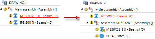
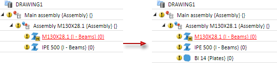
If the reference beam belongs to an assembly, the stiffener, too, will be assigned to this assembly as a main part.

Die Konfiguration der Steife erfolgt über die Registerkarten des Dialogfensters:
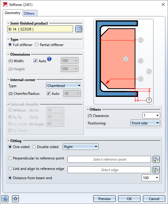
On this tab you specify the type, size and alignment of the stiffener.
|
Halbzeug |
Click the |
|
Typ |
Here you can select whether a Full stiffener or a Partial stiffener is to be fitted. |
|
Dimensions |
Here you specify the width of the stiffener. The width can either be calculated automatically or entered via value input. If you choose the automatic calculation, the width covering the area between the frontal flange edge and the web will be determined (rounded to whole millimetres). For partial stiffeners the height needs to be determined as well. |
|
Internal corner |
Here you determine the type of the stiffener. Possible options are:
Select the desired type and enter the chamfer length or the fillet radius, respectively. If you want values to be calculated automatically, activate the corresponding checkbox. |
|
External chamfer |
For partial stiffeners you have different options to determine the external chamfer: Depending on the selected option, further value input fields may then be active, e.g. fx, fy or Angle. |
|
Others |
Here you specify the width of the clearance and select the front side, the middle or the back side of the stiffener as reference side. |
|
Fitting |
Here you can choose between a One-sided and a Double-sided fitting. You have the following options to specify the position of the stiffener:
|
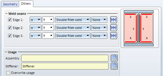
Here you define the weld seams and the usage of the stiffener.
Weld seams
Activate the checkboxes of the weld seams that you want to create between beam and stiffener:
For each edge you can select a type of thickness designation, the weld seam thickness, the weld seam type and the inspection category. In the listbox for the Inspection category you can select the test/inspection method according to DIN EN 1090. These inspection categories are predefined in the Configuration Editor at Modelling > Weld seams. They will be evaluated during creation of Weld Seam Test Protocols.
If you want to use the same settings for the other edges, click the Equate  icon.
icon.
Usage
Here you can assign a usage to the assembly of the selected beam and to the stiffener. If a usage has already been assigned to the assembly of the beam, the Overwrite usage checkbox can be used to specify whether the existing usage is to be kept or replaced by the usage type selected on the Others tab.

Connections + Variants (3-D SE) • Dialogue Window for Connections (3-D SE) • The Catalogue System for Connections + Variants (3-D SE)
|
© Copyright 1994-2020, ISD Software und Systeme GmbH |
Data protection • Terms and Conditions • Cookies • Contact • Legal notes and Disclaimer
 icon to select the type (e.g. Plates, Flat steels, Steel bars) and the material of the stiffener directly from the standard part catalogues.