Project: HiCAD Steel Engineering
"Civil Engineering functions" docking window > Steel Engineering > General> Bar Configurator
Use the Bar Configurator dialogue window to fill the area between 4 boundary beams, or the area between 4 edges of a sketch with bars. The placing of bars along composite edges is also possible.
Please note that the Bar Configurator can only be used for straight bars!
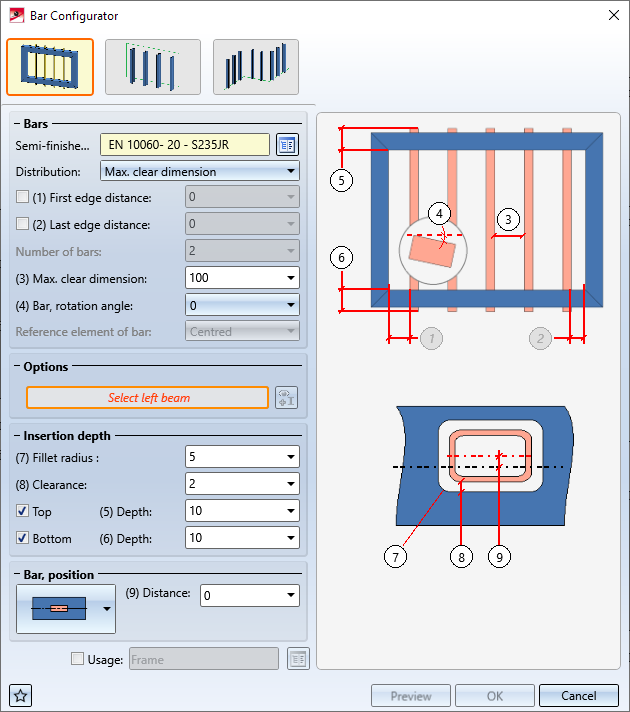
When you call the function, the Bar Configurator dialogue window will be displayed:
The following options are available:
|
|
|
|
|
|
|
|
The settings specified in the dialogue window can be saved as favourites and re-used at any time if desired. To do this, click the  symbol at the bottom left of the dialogue window.
More information on favourites management can be found in the Manage Favourites topic of the HiCAD Basics Help.
While the dialogue window is open you can click the Preview button to display a preview of the bars with their current settings. You can use the Zoom functions to enlarge or downsize the image.
Click OK to start the generation of the bars. The current status of the generation is shown in a progress bar.
The settings in the dialogue window can be saved as Favourites and reused at any time. To do this, click on the  at the bottom left of the window to activate the context menu. More about Favourites management can be found in the Manage Favourites topics of the HiCAD Basics Help.
 Please note:


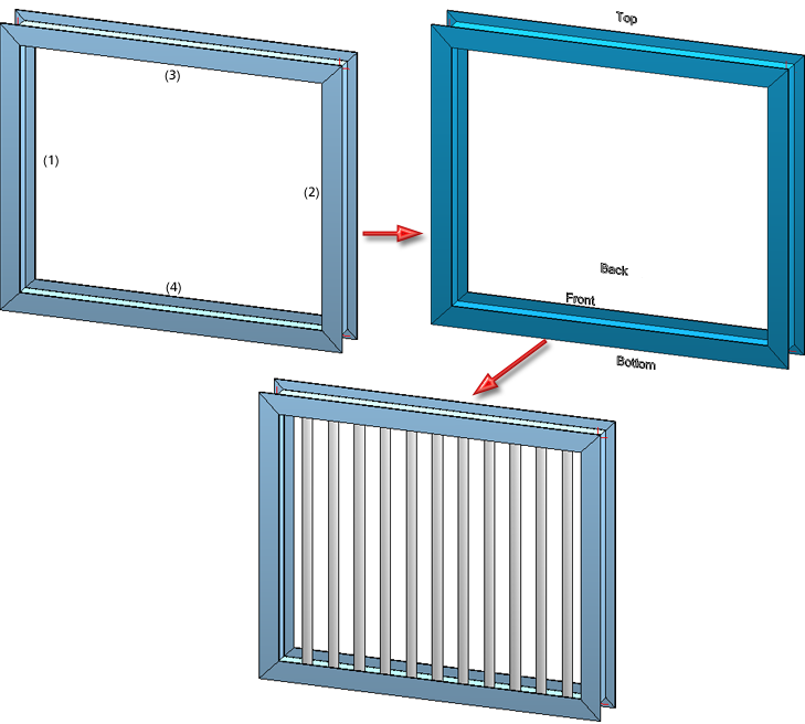
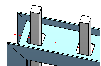
Use this function to insert bars in an area between 4 beams. The beams must be located in one plane, but need not necessarily be connected to each other.
Click the  symbol and identify 4 beams in the drawing in the following order:
HiCAD will then show you where (depending on the selected beams) the front/back and top/bottom sides are in the drawing. The info texts are aligned in Z-direction.
Insertion depth
Here you specify the insertion of the bars into the upper and the lower beam.
|
Fillet radius |
For bars with square cross-sections (e.g. square steels, flat steels, hollow profiles, ...) you can enter a fillet radius for the insertion hole. A prerequisite for this is a sufficient clearance.
|
|
Clearance |
Distance between bar and hole edges |
|
Depth, Top |
Insertion depth of bar in upper beam |
|
Depth, Bottom |
Insertion depth of bar in lower beam |
If you use I-, L-, T- or U-beams/profiles as semi-finished products for the bars, the input fields beneath Insertion depth will be greyed out.
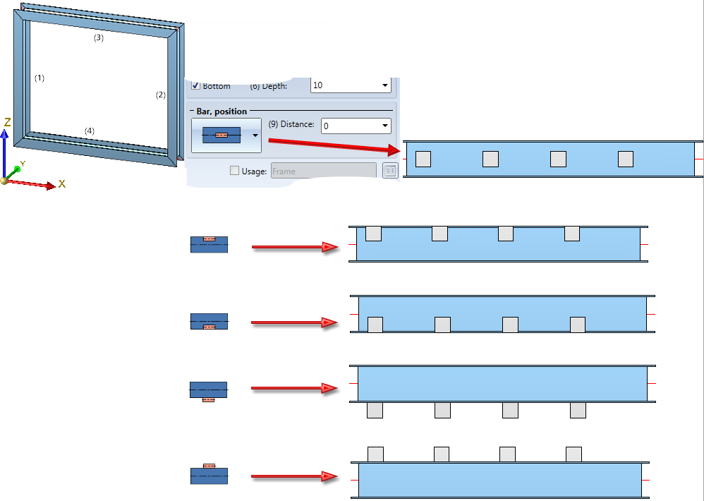
Bar, position
Choose the desired position of the bars. The following options are available. Possible are:
|
|
The bars are placed on the centre axis of the selected area. |
|
|
The bars are placed at the rear on the inner side of the selected area. |
|
|
The bars are placed at the front on the inner side of the selected area. |
|
|
The bars are placed at the rear of the selected area. |
|
|
The bars are placed at the front of the selected area. |
|
Distance |
Here you can additionally specify an offset in Y-direction. |
Example:
4 bars are to be placed into the framework with the settings shown below. The top view illustrates the different placing options.
|
Semi-finished product |
Select a semi-finished product for the bars. If you click the |
|
Division |
This option determines the division of the area by the inserted bars, influencing also the number of inserted bars. The following options are possible:
If you want to specify a particular border distance, enter the required values. If you do not want the border distance to depend on the maximum clear distance, deactivate the checkbox.
|
|
Bar, rotation angle |
If you want to rotate the bar before its insertion, enter the desired rotation angle here. |

Use this function to insert bars into an area formed by a rectangular sketch or by 4 edges.
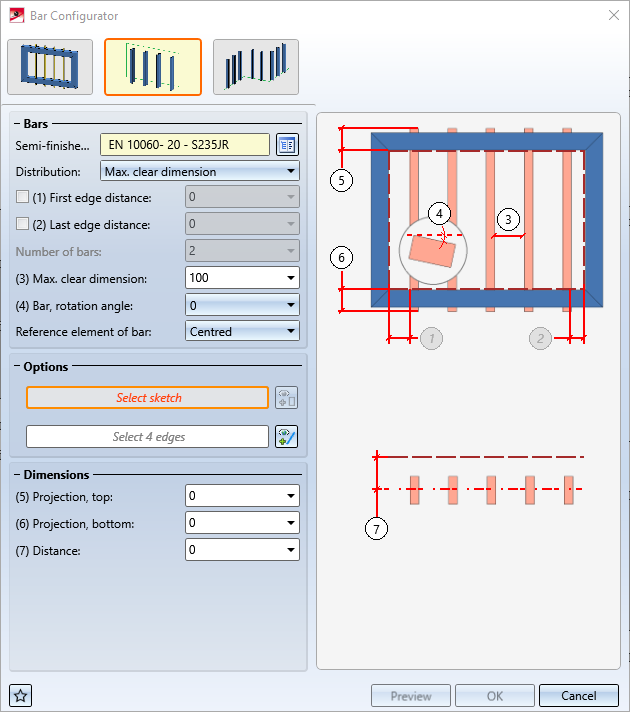
To identify a sketch in the drawing, click the  symbol and select the 4 edges of the sketch.
To identify 4 edges located in one plane, click the  symbol and select the desired edges. These edges need not necessarily be connected.
The edges must be selected in the following order:
HiCAD will then show you in the drawing, where the (depending on the selected edges) front/backand top/bottom sides are in the drawing. The info texts are aligned in Z-direction.
Dimensions
|
Projection, top |
Excess length of bar with regard to the selected upper edge |
|
Projection, bottom |
Excess length of bar with regard to the selected lower edge |
|
Distance |
Determines the distance of the bars to the plane defined by the selected edges. |
Bars
The setting options in this area correspond to those of the Bars between beams function.
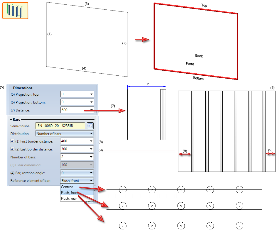
(1) - (4) Selected edges of a rectangular sketch, (5) Settings, (6) Result in front view, (7) Distance in side view, (8) First border distance, (9) Last border distance

Use this function to place bars along composite edges.
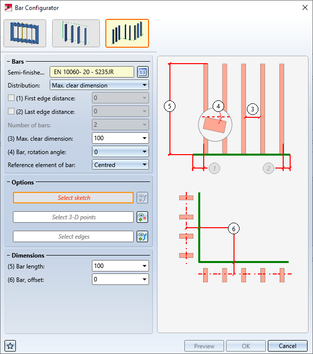
The c-edge is determined by the following parameters:
 Selection of a sketch
 Selection of 3-D points Selection of edges
Dimensions
|
Bar length |
Length of bars |
|
Bar, offset |
Distance of the bars to the sketch or facet |
Bars
The setting options in this area correspond to those of the Bars between beams function.
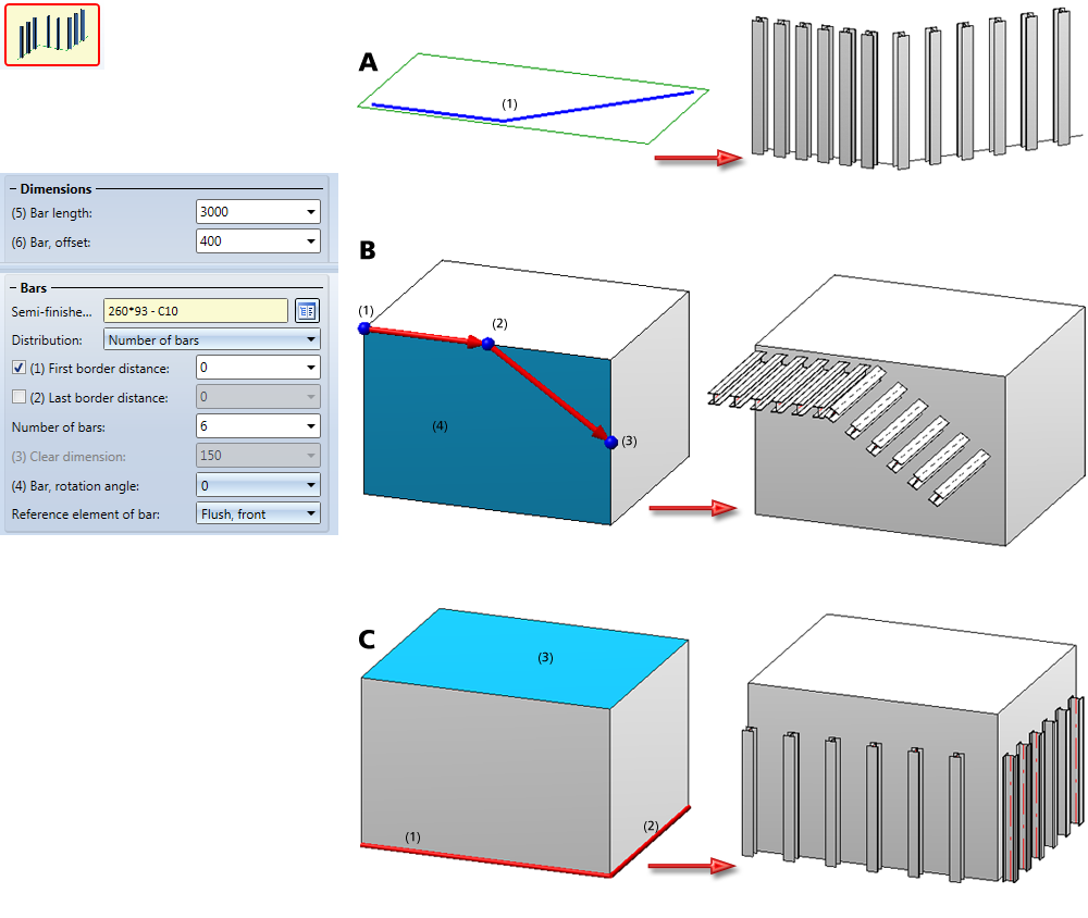
A: Bars along a sketch (1)
B: Bars along a c-edge determined by 3-D points: (1)-(3) selected 3-D points, (4) selected facet
C: Bars along a 3-D c-edge: (1) and (2) selected edges, (3) selected facet

Connections + Variants (3-D SE) • Dialogue Window for Connections (3-D SE) • The Catalogue System for Connections + Variants (3-D-SE)
|
© Copyright 1994-2020, ISD Software und Systeme GmbH |
Data protection • Terms and Conditions • Cookies • Contact • Legal notes and Disclaimer


 symbol you can make your selection directly from the HiCAD catalogue.