Project: HiCAD Steel Engineering
"Civil Engineering functions" docking window > Steel Engineering > Connections > Front side to web/flange side > Angle > Angle connection, one-sided (1305)
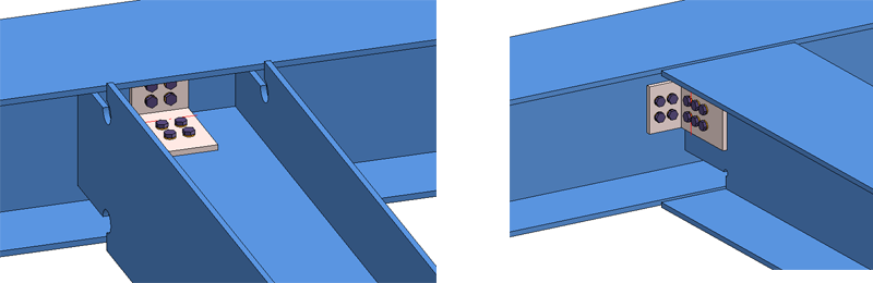
Use this function to connect two beams by flexible angle steels. The connection can be user-defined or according to DAST. For DAST connections you can choose between
The function can be applied to parallel and perpendicular flanges.
Angle connection, one-sided
Proceed as follows:
The configuration of the angle connection takes place via the tabs of the dialogue window.
Click the Preview button to display a preview of the connection, based on the current data. If you want to correct the data, make the desired modifications and click Preview again to update the preview. Click OK to insert the connection with the specified data, and the dialogue window will be closed. Click Cancel to close the dialogue window without inserting/changing the connection.
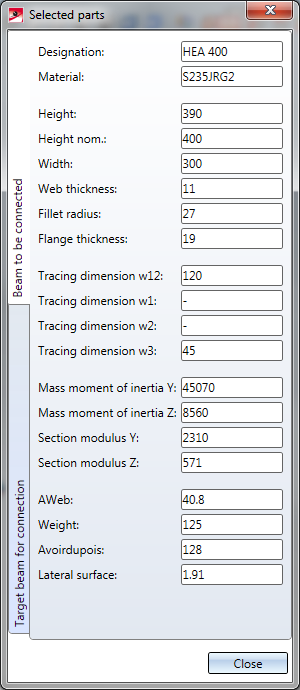
Click the  symbol to display information on the previously identified beams, e.g. type, material, dimensions, etc. Data input and changes are not possible here.
The settings in the dialogue window can be saved as Favourites and reused at any time. To do this, click on the  at the bottom left of the window to activate the context menu. More about Favourites management can be found in the Manage Favourites topics of the HiCAD Basics Help.
 It depends on the settings on the Bolting tab how the angle connection will be inserted into the part structure.

The insertion of the angle connection can take place as a user-defined connection or according to DAST tables. The input/selection fields are initialised with values, depending on the selected configuration or the selected connection type, and can be modified if desired.
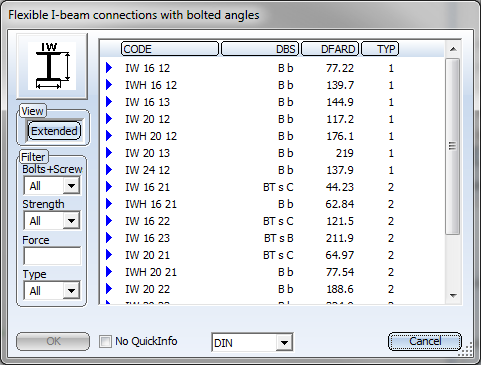
The data for the typified Steel Engineering connections according to DSTV/DAST are in stored in tables in HiCAD: To apply the data for the related parts such as angle steel, plates, screws etc. from these tables, select the connection type IW or IG first, by clicking on the appropriate symbol. HiCAD will then display a selection of possible connections. if you want only DAST-conform connections to be displayed, activate the corresponding checkbox beforehand. If the checkbox is not active, the non-conform connections will be highlighted in a different colour.
Click the Extended button to show more data of the possible connections. You can set one or several filters (Bolts+Screws, Strength...) to limit the selection options. Select the desired option and close the window with OK. The designation of the selected DAST connection will then be shown in the input field.

After selection of the DAST connection, the contents of the tabs will be adjusted accordingly. Settings that are not possible for the selected connection will be greyed out. If you have changed any settings on the tabs that do not correspond to the preset values of the selected DAST connection, this will be indicated by a  symbol next to the DAST designation.
To restore the settings to defaults, click the  symbol. To remove the assignment to the DAST presettings, e.g. because you prefer a user-defined connection, click the
  symbol.
User-defined insertion
If you want to insert the connection without using the DAST tables, the DAST input field must be empty.

You may need to remove the assignment to a DAST table.
The angle connection is configured via the tabs:
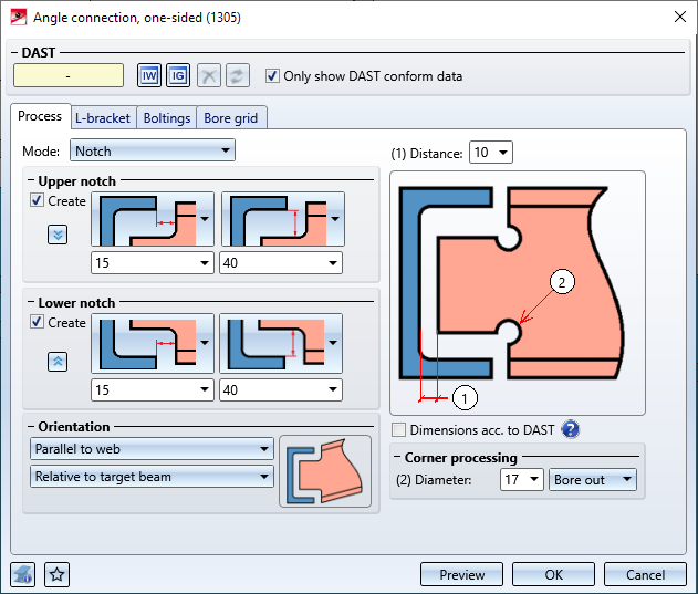
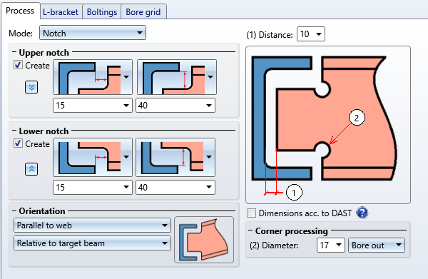
Here you specify the distance between the end of the beam to be connected and the web of the target beam. Furthermore, you specify, via the Mode selection list, the way in which the connection is to be made.
You can choose between two Modes for the connection:
| Notch |
Required are the distance between the end of the beam to be notched and the web of the target beam. If you want to apply a notch to the beam to be connected, activate the corresponding checkbox. The horizontal and the vertical offset for the upper and the lower notch can be specified separately. You determine via the graphical selection boxes which offsets will be specified here.
The settings for the upper notch can be applied to the lower notch with a click on the The Orientation can be parallel to the web or vertical to the axis of the target beam or the notched beam.
For Corner processing you can choose between the following two options:
If the Dimensions acc. to DAST checkbox is active, the next higher values from the "DSTV Typified Structural Steel Engineering Connections" (Volume 1, "IK Notches" chapter) will be used for the notch length, notch height and the fillet. |
||||||||||||||||||||||||
| Trim |
If you want to trim the beam to be connected, you can choose between an orientation parallel to the web or vertical to the axis of the target beam. |
||||||||||||||||||||||||
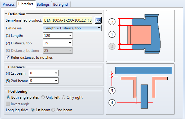
On this tab you define the angle steel of the connection, the so-called "L-bracket". You can also specify whether you want to use two L-brackets, only the left one, or only the right one for the connection.
|
Semi-finished product |
Click the |
|
|
Geometry |
For the definition of the geometry the following four procedures are available, which can be selected from the Define via listbox.
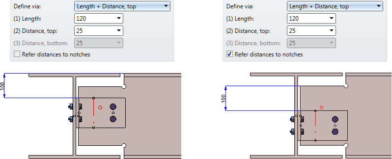
The specified distance can either refer to the top/bottom edge of the flange or - if the Notch processing mode was selected on the Processing tab - to the notch. In the latter case, activate the Refer distances to notches checkbox.
|
|
|
Clearance |
Here you can enter a clearance value if desired, i.e. the distance of the plate from the second identified beam. |
|
|
Positioning |
Here you specify whether both angle plates or only the right one, or only the left one are to be inserted, and where the long leg side is to be located. If you have selected only one angle plate, you can invert it by activating the Invert angle checkbox. |
|
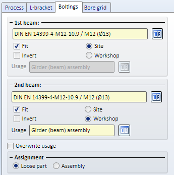
Here you define the bolting, separately for the two beams. First, specify the components of the bolting, e.g. the type of the bolt, the bore diameter etc. click the  symbol to specify the components of the bolting. The procedure is the same as with the normal Steel Engineering bolting function.
In addition, you can specify:
If you select the Workshop production type, you can click the symbol to select the Usage from the same-named catalogue. The default setting is Girder (beam) assembly (for example, part annotation in workshop drawings can take place depending on usage). If a usage has already been assigned to the assemblies of the beams, the Overwrite usage checkbox can be used to specify whether the existing usage is to be kept or replaced by the usage type selected on the Boltings tab.
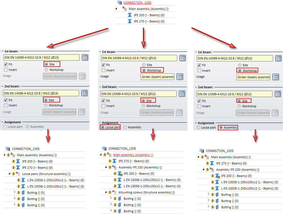
A maximum of 3 Bolting groups are created for this angle connection. The assigning of these bolting sets depends on the settings on the Boltings tab.
If you have chosen the production type Workshop for one of the beams, you can select beneath Assignment, by activating the corresponding option, whether the bolting groups of this beam are to be assigned to the assembly of the beam, or to a structure assembly called Loose parts on the same level as the assembly of the beam. The L-brackets of the connection are assigned to the assembly of the beam with the production type Workshop.
If you have selected the production type Site for both beams, the L-brackets and the bolting groups will be assigned to a structure group called Loose parts.
The bore grid determines the arrangement of the bores for the angle steel.
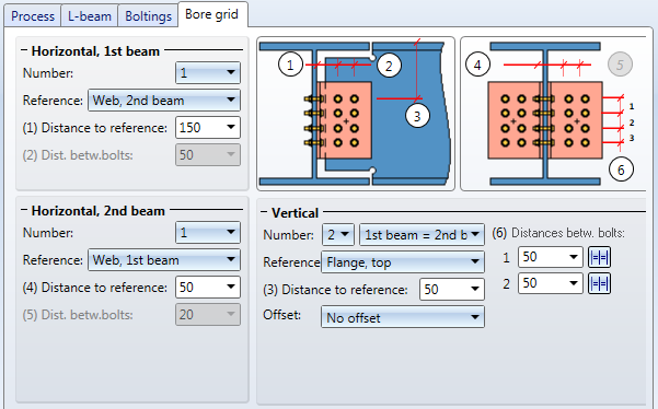
Horizontally, the grid can be specified separately for the beam to be connected and the target beam for the connection. For each situation you need to specify the Number of bores, a Reference and the Distances between bolts.
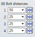
For the vertical settings, also enter the number of bores and specify, via the corresponding selection box, whether you want the number of bores to be identical for the 1st beam and the 2nd beam, or if you want one fewer row for one of the beams. In addition to the reference and the distance to the reference you can select an Offset to the reference edge.
| Horizontal, 1st beam - Reference: | Horizontal 2nd beam - Reference: | Vertical - Reference |
|---|---|---|
| End of 1st beam | Internal distance | Centred, rel. to angle |
| Web, 2nd beam | Web, 1st beam | Flange, top |
| Tracing dimension, angle | Tracing dimension, angle | Angle, top |
| Flange, bottom | ||
| Angle, bottom |

Connections + Variants (3-D SE) • Dialogue Window for Connections (3-D SE) • The Catalogue System for Connections + Variants (3-D SE)
|
© Copyright 1994-2020, ISD Software und Systeme GmbH |
Data protection • Terms and Conditions • Cookies • Contact • Legal notes and Disclaimer


 symbol for the lower notch.