Project: HiCAD Steel Engineering
'Civil Engineering functions' docking window > Steel Engineering > Connections > Web/Flange to Web/Flange > Cross-bracing (2603)
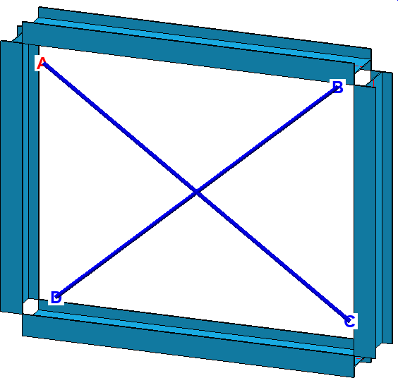
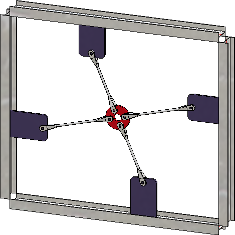
This design variant combines two, three or four beams or plates with a cross-bracing of the type
Here the beams/plates are connected to a circular disc or a cross anchor by a Besista tension rod system consisting of tension rod and rod anchors.
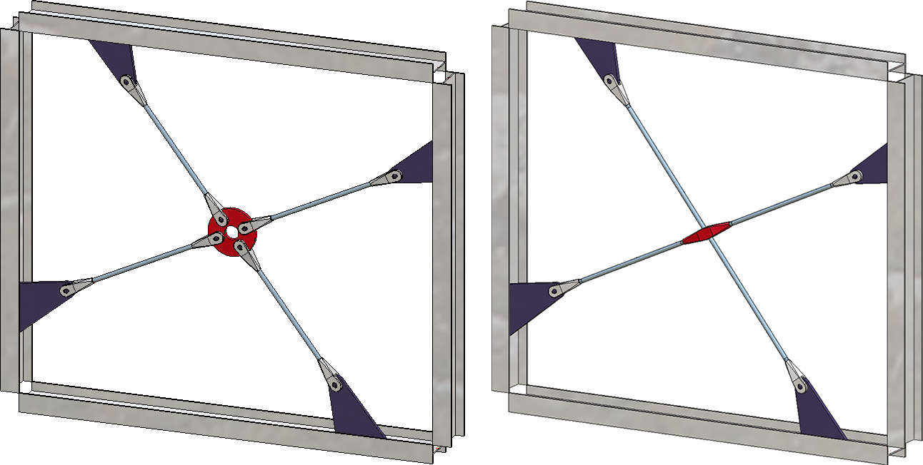
Cross-bracing "Besista. Left: With circular disc; Right: With cross anchor
When connecting beams, the cross-bracing usually automatically supplies the gusset plates. However, you also have the option of fixing the cross-bracing to plates that already exist on the beam.
Please note that when fixing to plates, the plates must be aligned with each other.

Tabs
The configuration of the cross-bracing is defined on several tabs:
Favourites
The settings in the dialogue window can be saved as Favourites and reused at any time. To do this, click on the  at the bottom left of the window to activate the context menu. More about Favourites management can be found in the Manage Favourites topics of the HiCAD Basics Help.
Buttons
|
Preview |
Shows you a preview of the cross-bracing according to the current settings. You can enlarge or downsize the preview image with the help of the zoom functions. |
|
OK |
Starts the generation of the cross-bracing. The progress of the generation will be shown in a progress bar. After completed generation, the dialogue window will be closed. |
|
Cancel |
Closes the dialogue window without generating the cross-bracing. |
![]() Please note:
Please note:
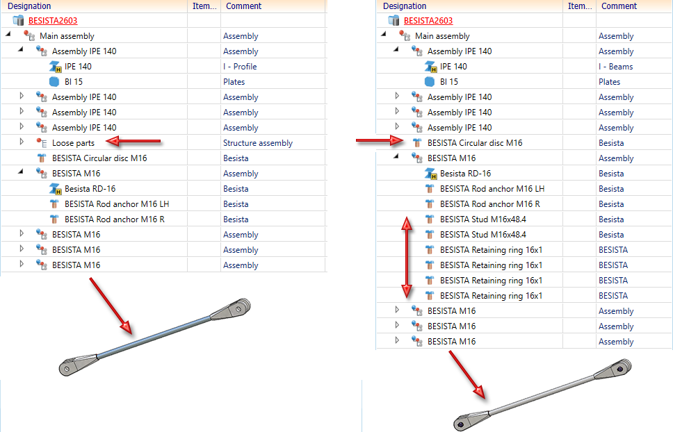
If the Create assembly: Loose parts checkbox on the Semi-finished products tab is activated, the circular disc/cross anchor and the studs and retaining rings for fixing the tension rod system are combined into a structure assembly called Loose parts. If the checkbox is deactivated, the studs and retaining rings are assigned to the assemblies of the corresponding tension rod system. In this case the circular disc/cross anchor is inserted as an individual part.
The centre of the circular disc is always in the intersection point of the tension rods, and not always necessarily in centred position between the beams.
Please note:
If you subsequently edit a cross-bracing (double-click on the feature) and then select a different number of beams, any existing rework and dimensioning of parts of the cross-bracing will be lost. HiCAD then displays a corresponding message: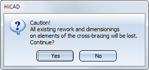

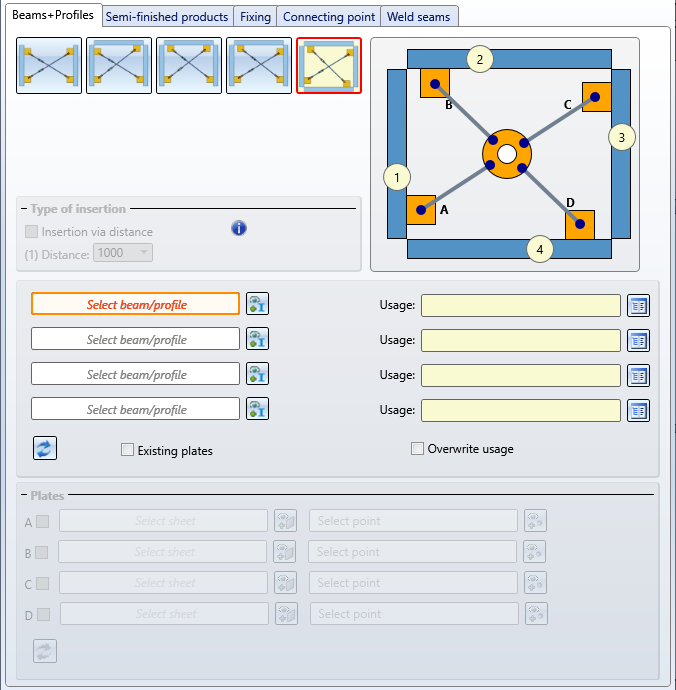
On this tab, you determine which beams or plates are to be connected to each other by the cross-bracing.In case of beams supplies the design variant usually automatically determines the gusset plates for the connection. Alternatively, you can also use plates that already exist on the beam as gusset plates. This can be useful, for example, if you want to install two cross-bracings between two beams and the second cross-bracing is to be attached to the gusset plates of the first cross-bracing.
|
|
The cross-bracing is inserted between two beams. If desired, the distance between the lower edge of the first connecting plate on the beam and the upper edge of the second connecting plate on the beam can be determined under Type of insertion. If no distance is entered, the insertion is applied centrally. |
|
|
Three beams are connected here. The first diagonal is installed between beams (1) and (2), the second diagonal between beams (3) and (1).
|
|
|
Three beams are connected here. The first diagonal is installed between beams (1) and (2), the second diagonal between beams (3) and (2).
|
|
|
Three beams are connected here. The first diagonal is installed between beams (1) and (3), the second diagonal between beams (3) and (2). |
|
|
The cross-bracing connects four beams. The first diagonal is installed between beams (1) and (3), the second diagonal between beams (4) and (2). |
Activate the desired installation option and then select - if necessary by clicking on the  symbol - the desired beams. For each beam you can select a usage from the catalogue. If a usage is already assigned to the beams' assemblies, you can use the Overwrite usage checkbox to specify whether the usage should be retained or replaced by the usage selected on the Beams+Profiles tab.
 Please note the following when selecting the beams:
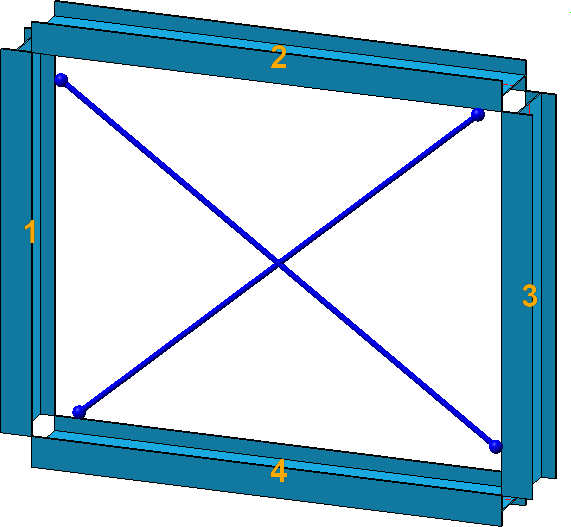
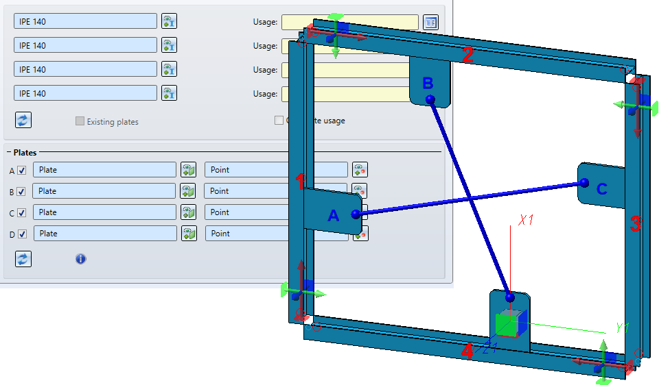
After selecting the beams, they are visualized in the model drawing - including diagonals.
Use the  symbol to restore the settings on this tab to defaults.
The design variant automatically supplies the gusset plates for the connection. Alternatively, existing plates on the beam can also be used as gusset plates. This can be useful, for example, if you want to insert two cross-bracings between two beams and the second cross-bracing is to be attached to the gusset plates of the first cross-bracing.
If the cross-bracing is to be fixed to plates that already exist on the beams, you can select the corresponding plates in addition to the beams. To do this, activate the corresponding checkbox in the Plates area, select the plate and specify a point for the centre of the fixing.
Please note the following:
 i
i
If you want to insert cross-bracing between plates - independent of beams - activate the Existing plates checkbox. Then activate the corresponding checkbox in the Plates area, select the plate and specify a point for the centre of the bore grid for the fixing.
Please note the following:
In this area you can select the following by clicking on the respective  symbol
directly in the corresponding standard parts catalogues. Tension rod systems can be found in the Steel Engineering > General management > BESISTA Tension rod system, gusset plates in the Semi-finished products > Plates catalogue.

Left: Settings for Type of insertion: With circular disc; Right: Settings for Type of insertion: With cross anchor
In addition, the following can be specified by activating/deactivating the corresponding checkboxes:
Create assembly: Loose parts
If this checkbox is activated, the circular disc or cross anchor and the studs and retaining rings for fixing the tension rod system are combined into a structure assembly called Loose parts. If the checkbox is deactivated, the studs and retaining rings are assigned to the assemblies of the corresponding tension rod system. In this case the circular disc or cross anchor is inserted as an individual part.
Circular disc: Own production (only relevant for Type of insertion: With cross anchor)
The size of the circular disc is automatically determined by the position of the rod anchor (depth and width of the slot, position of the bore). If the checkbox Circular disc: Own production is activated, a corresponding steel engineering plate is installed. If the checkbox Circular disc: Own production is deactivated, the appropriate circular disc is automatically selected from the catalogue Steel Engineering Standard Parts > Tensioning elements > Besista > Circular disc.
The centre of the circular disc is always at the intersection of the tension rods and not always in the centre of the beams .
Studs: Create / Retaining rings: Create
With these checkboxes you define if studs and retaining rings should be inserted to fix the anchor rods.
Here you determine how the diagonals are to be fixed to the beams.
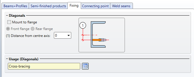
Under Diagonals you determine whether the gusset plates should be fixed to the flange of the beams and if so, whether the fixing should be done at the front or the rear flange.
Additionally you have the possibility to specify the distance from the centre axis. This value determines the insertion point of the first plate at the first identified beam.
The assembly with the tension rod system can be assigned a usage.
 When connecting plates, the settings on this tab are inactive.
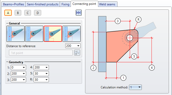
Here you define how the gusset plates should be connected to the beams and the anchor rods. Furthermore, the geometry of the gusset plates is defined here.
|
For each of the gusset plates can be determined here,
These settings are defined separately for each gusset plate by clicking on the corresponding letter symbol and then making the desired settings. By clicking on the The connection is visualized in the model drawing.
|
|||||||||||||||||||||
|
General |
By selecting one of the symbols you determine how the position of the gusset plate is to be determined - by a point specification or a distance specification. By selecting the points you also determine the assignment to an assembly. If an assembly already exists with the affected beam, the connecting beams are inserted as sub-parts of the assembly. Otherwise a new assembly is created with the affected beam as main part and the connecting plates are inserted as sub-parts of this assembly. |
|||||||||||||||||||||
|
|
Point as intersection point of the beam axis and the round steel axis of the tension rod system |
|||||||||||||||||||||
|
|
Point as plate start |
|||||||||||||||||||||
|
|
Distance Beam start - Plate start |
|||||||||||||||||||||
|
|
Distance Beam start – Intersection point of axes of beam and round steel of tension rod system |
|||||||||||||||||||||
|
Geometry |
Here you determine the geometry of the gusset plates. Two calculation methods are available for this purpose, which you can choose in the selection box below the graphic.
|
Not all options are available when Plates has been selected on the Beams+Profiles tab.
On this tab you define which weld seams should be generated on the gusset plates.
Activate or deactivate the corresponding checkboxes to specify where weld seams are to be created. For each gusset plate you can set the Type of thickness designation, the Weld seam thickness, the Weld seam type and the Inspection category. If you want to apply the same settings to all gusset plates, click on the Equate  symbol.
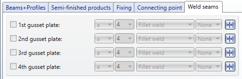
For continuous HV and HY weld seams, enter 0 as the weld seam thickness.
The settings of this tab are inactive if plates are selected on the Beams+Profiles tab.

Connections + Variants (3-D-SE) • Dialogue Window for Connections (3-D SE) • The Catalogue System for Connections + Variants (3-D SE)
|
© Copyright 1994-2020, ISD Software und Systeme GmbH |
Data protection • Terms and Conditions • Cookies • Contact • Legal notes and Disclaimer