Project: HiCAD Steel Engineering
"Civil Engineering functions" docking window > Steel Engineering > Connections > Individual beam/profile > End plate (2102)
Use this function to connect an end plate to a beam. The plate can be inserted with a bolting, pre-drilled, with or without filler plates, and with or without base. If desired, weld seams can be directly inserted.
Possible beam types are I-beams, U-beams, L-beams, T-beams, Z-profiles, pipes and hollow profiles.
Allowed semi-finished products for the plate are simple Plates, Flat steels, FLUTZ profiles, A3 Steel bars by Frankstahl or C3 Stainless steel bars.
Proceed as follows:
Click the Preview button if you want to display a preview of the plate based on the currently entered data. If you want to modify the current data, apply the required changes and click Preview again to update the preview. Click OK to insert the plate according to the current data and close the dialogue window. If you click the Cancel button, the window will be closed, and the specified or changed connection will not be inserted.
Symbols:
|
|
Selected parts Click on this symbol to show information on the previously identified beams, such as the type of the beam, the material, the dimensions, etc. Value inputs and changes are not possible here.
|
|
|
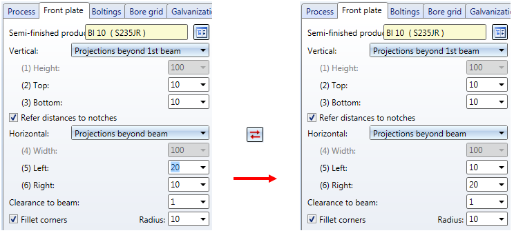
Invert concerned connection values horizontally Click on this symbol to switch specified values horizontally, i.e. right and left. For instance, this can be done for
|
|
|
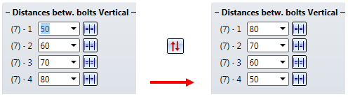
Invert concerned connection values vertically Click on this symbol to switch specified values vertically, i.e. top and bottom. For instance, this can be done for
|
|
|
The settings in the dialogue window can be saved as Favourites and reused at any time. To do this, click on the |
![]() Please note:
Please note:
 Important:
 symbol at the OK button. When you move the cursor over the symbol, an explanatory text will be displayed.
The configuration of the end plate connection takes place via the tabs of the dialogue window:
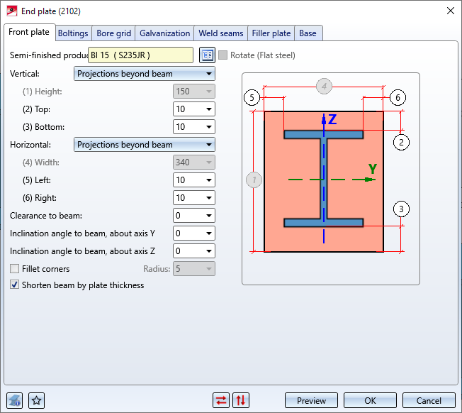
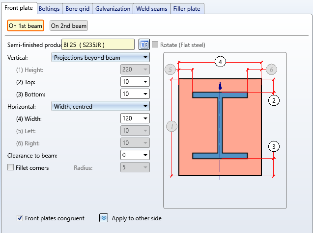
On this tab you specify the data of the plate.
|
Semi-finished products |
Click the |
||
|
The values beneath Vertical and Horizontal determine the height and width of the plate and its projection. The following, different procedures are available: |
|||
|
Vertical |
|
||
|
Horizontal |
|
||
|
Clearance to beam |
If desired, enter a value for the clearance here, i.e. the distance of the plate to the beam. The value can be specified separately for the first and the second beam. |
||
|
Fillet corners |
If you want the corners of the front plate to be filleted, activate this checkbox and enter a fillet radius. The value can be specified separately for the first and the second beam. |
||
|
Shorten beam by plate thickness |
If you activate this checkbox, the plate thickness will be subtracted from the length of the selected beam. |
||
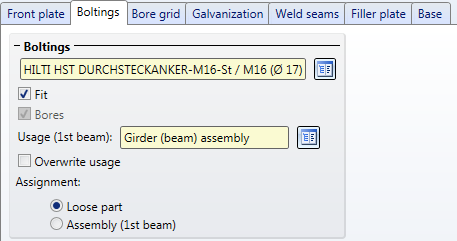
Here you specify the bolting, i.e. the bolt type, diameter etc. Click on the  icon and select the components of the bolting. The default setting is DIN EN ISO 4014-M16-5.6 / M16 (⌀ 17,5). Proceed in the same way as you would do with the Steel Engineering Bolting function.
The bolting will only be inserted if the Fit checkbox is activated.
Usage and Assignment
In the Usage field you can specify which usage is to be assigned to the assembly of the beams. If a usage has already been assigned to the assembly of the beam, the Overwrite usage checkbox can be used to specify whether the existing usage is to be kept or replaced by the usage type selected on the Bolting tab.
Next to Assignment you can specify to which assembly the boltings are to be assigned. If the Loose part option is active, the boltings will be placed in an assembly called Bolting and assigned to the structure assembly Loose parts, or otherwise to the assembly of the selected beam.
If the Assembly (1st beam) option is activated the Bolting assembly and the reinforcement plates will be assigned to the assembly of the first beam.
If the Lose parts option is activated the Bolting assembly, the reinforcement plates and the filler plates will be assigned to the structure assembly Loose parts. This structure assembly is placed on the same level as the assembly of the first beam.
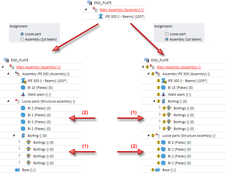
(1) Bolting, (2) Reinforcement plates, (3) Filler plates
Please note that the settings for the Usage and the Assignment must be made before the creation of the assembly structure of the connection. After clicking the Preview button, and also after insertion of the connection, a change of these settings will no longer be possible.
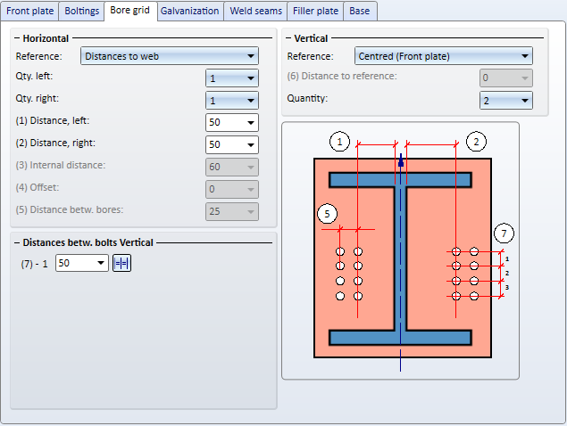
If you have activated the Fit and Bores checkboxes on the Boltings tab, the bore grid will determine the arrangement of the bores in the end plate.
First you need to choose a reference for the Horizontal and Vertical settings. Further value inputs depend on the selected reference.
|
Horizontal, Reference |
Inputs |
|
Distances to plate edge |
|
|
Internal distance
|
|
|
Distances to web |
|
|
Vertical, Reference |
Inputs |
|
Centred |
|
|
Reference beam, upper edge |
|
|
Front plate, top |
|
|
Reference beam, lower edge |
|
|
Front plate, bottom |
|
|
You can use different distances between bores in vertical direction. If all bores are to have the same vertical distance, you can also simplify the value input: Enter the distance value in one of the input fields and click the Equidistant |
|
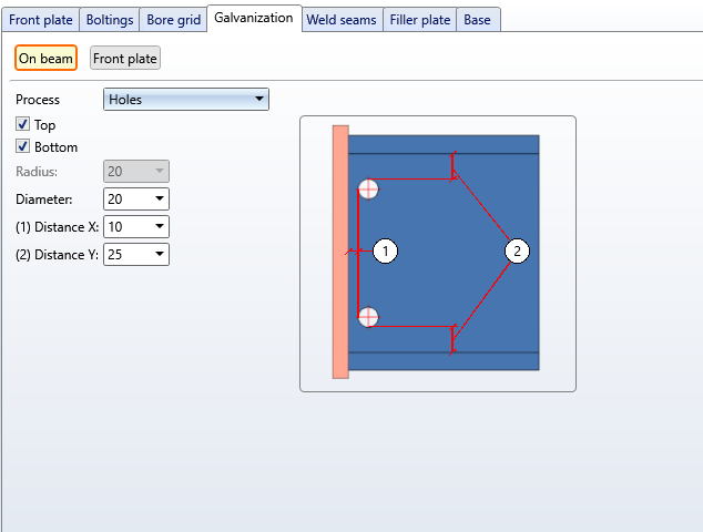
Here you can choose whether you want to apply bores for galvanization to the end plate and the reference beam. Activate the corresponding tabs on the left hand side of the window and enter the desired diameter.
On beam
Here you choose a processing. Possible are:
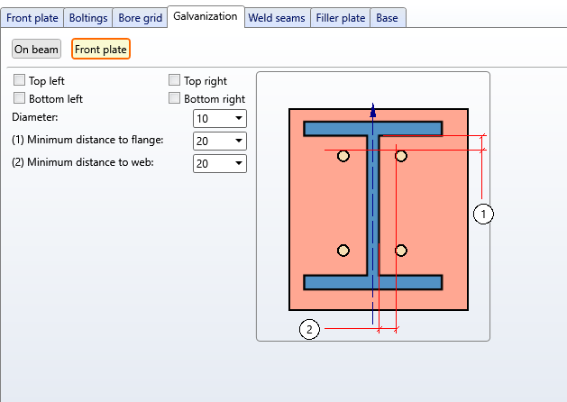
Front plate
Specify by activating the corresponding checkboxes which holes are to be created. Enter the hole diameter and the minimum distance to the web and the flange.
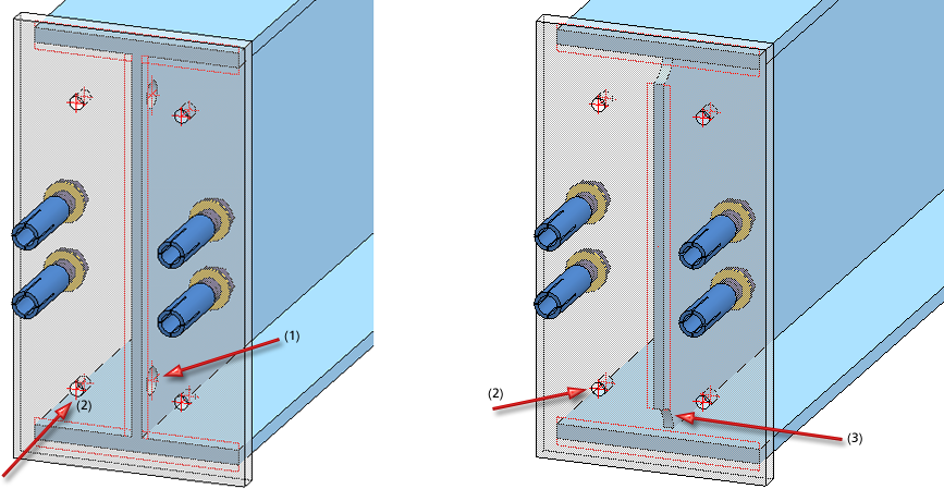
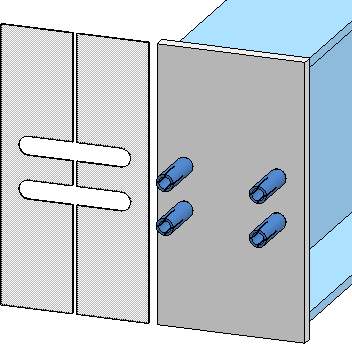
(1) Processing on beam: Web cut top/bottom; (2) Holes in plate; (3) Processing on beam: holes top/bottom
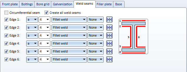
On this tab you can specify which weld seams are to be created:
For each edge you can select the type of the thickness designation, the weld seam thickness the weld seam type and the inspection category. If you want to use the same settings for all edges, click the Equate symbol.
For continuous HV and HY weld seams, enter 0 as the weld seam thickness.
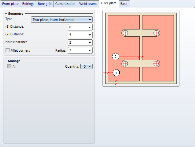
If you want to insert filler plates between the two front plates, you can specify the number, the type and the size of these plates on the Filler plate tab.
The following geometries for filler plates are available:
Depending on the selected geometry type, enter the required distances and the hole clearance. The hole clearance always refers to the bolting.
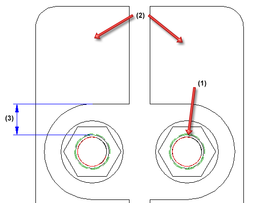
(1) Bolt diameter, (2) Two-piece filler plate, (3) Hole clearance
Beneath Manage you can specify the number of filler plates.
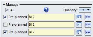
For each filler plate, select the desired plate type in the catalogue . Specify, by activating the corresponding checkboxes, whether the filler plate is to be pre-planned or not. If a filler plate is pre-planned, the 1st beam will be shortened by the thickness of the filler plate. Non-pre-planned filler plates will be created next to the connection.
Activate the All checkbox to set all filler plates to Pre-planned in one step.
Please note that non-pre-planned filler plates will be shown in transparent representation in the drawing, i.e. they will be assigned to Layer 40.
Non-pre-planned filler plates
Filler plates are not assigned to the assembly of the 1st beam, but are placed in a separate structure assembly with the name Loose parts. Also, the usage Filler plate will be assigned to filler plates.
If the bore grid is too narrow, preventing the insertion of the filler plates, the connection will not be created, but the failed operation will be recorded in the feature log:
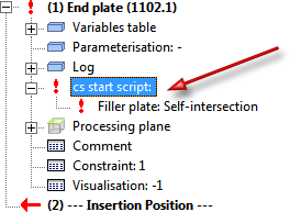
You can then double-click the feature and correct the settings.
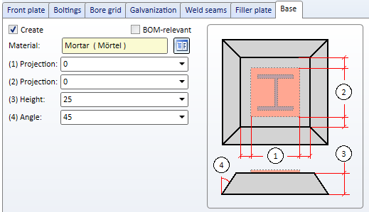
If you want to insert a base, you can specify the data for the base here.
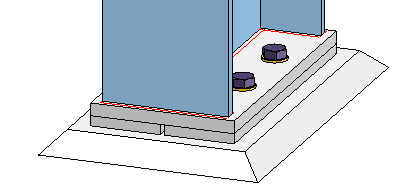
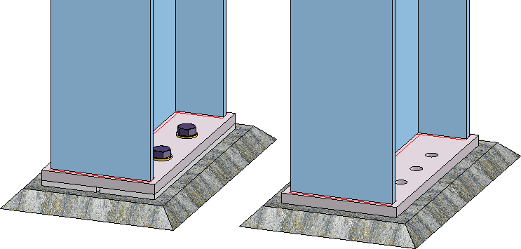
Plate with filler plate and base

Connections + Variants (3-D SE) • Dialogue Window for Connections (3-D SE) • The Catalogue System for Connections + Variants (3-D-SE)
|
© Copyright 1994-2020, ISD Software und Systeme GmbH |
Data protection • Terms and Conditions • Cookies • Contact • Legal notes and Disclaimer