
Project: HiCAD Steel Engineering
Steel Engineering > Plate, new > Fit stiffeners
Stiffeners can be fitted, with (internally or externally) chamfered or filleted corner, with one side or two sides, as partial or full stiffeners.
You define the position of a stiffener via the distance from the beam end, the distance from the fitting point or by specifying a fitting point. To define the distance, you can choose the front side, the middle or the reverse side of the stiffener as a reference point.
Fitting aligned to the front side of the stiffener
Once you have activated the Stiffener function, first identify the beam to which you want a join to be made. The selection window for stiffeners is displayed.
|
Fitting |
By activating the relevant option, you choose the front side, the middle or the reverse side of the stiffener as a reference here. The preview image is updated accordingly, depending on the option selected You define the position of a stiffener by:
In addition, by activating the Adjust position dynamically checkbox , you can define that the stiffener is automatically adjusted whenever there is a feature recalculation. |
|
Type, Sides, Internal corner |
You can choose here whether you want
You enter the values for the chamfer/ radius in the lower section of the window. |
|
Specifications for full stiffeners |
If you have selected the full stiffener as the stiffener type, enter the chamfer length/ fillet radius and clearance, depending on the corner option selected. If you want the chamfer length/fillet radius to be determined automatically, activate the Automatic Chamfer/Fillet checkbox. |
|
Specifications for partial stiffeners |
Partial stiffeners provide various options for determining the outer chamfer. Depending on the option selected, further input fields, e.g. fx, fy or Angle, are then active in the value input area. As for full stiffeners, you also enter the chamfer length/ fillet radius and clearance here. If you want HiCAD to determine the chamfer length/fillet radius automatically, activate the relevant checkbox. In addition, define the height of the partial stiffener in the Height field. |
|
Beam and Width |
The stiffener can be fitted as a plate, flat steel or broad flat steel. The width of the stiffener is determined automatically or by entering a value. If you selected the automatic calculation, the calculated width will be displayed in the (then greyed out) input field. |
|
Plate thickness and Material |
You choose the thickness of the stiffener in the selection list (SIZE) and the material in the list box (Type) below it. |
![]() Notes:
Notes:

After completion of all required settings in the Stiffener dialogue window, confirm them and close the window with OK.
If you have chosen to insert the stiffener via a fitting point, identify this point. The stiffener is fitted directly. HiCAD provides several solution options for partial stiffeners.
Once HiCAD has fitted the stiffener, you can use the selected settings to insert more stiffeners. If you want to end the function, press the right mouse button.
(1) Full stiffener, fitted centrally with two sides, internally filleted
(2) Full stiffener, with two sides, fitting: Front side, internally filleted
(3) Partial stiffener, with two sides, fitting: Reverse side, externally filleted
(4) Partial stiffener with one side, fitting: Centre with offset, chamfered
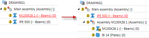
 If the reference beam is a main part that does not belong to an assembly, an assembly will be formed, with the beam as assembly main part and the stiffener as sub-part.
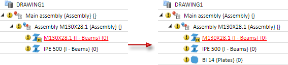
If the reference beam belongs to an assembly, the stiifener will also be assigned to this assembly as a sub-part.

Plates (3-D SE) • Steel Engineering Functions
|
© Copyright 1994-2020, ISD Software und Systeme GmbH |
Data protection • Terms and Conditions • Cookies • Contact • Legal notes and Disclaimer