NCX
Drawing > Save/Print... > Save as > Further... > NCX 
Use this interface to prepare HiCAD data for export to an NC machine. It depends on the machine type whether the DSTV-NC or the NCX interface will be chosen.
 Only itemized parts will be exported!
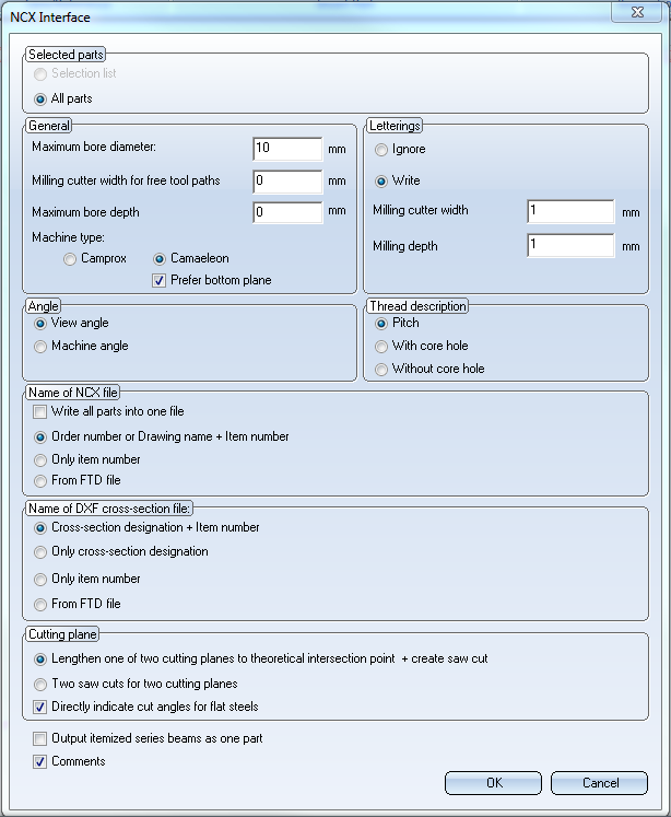
The dialogue window is composed of the following areas:
- Selected parts,
- General,
- Letterings,
- Angle,
- Thread description,
- Name of NCX file / DXF cross-section file,
- Cut planes
- Further options
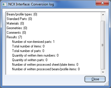
Specify the required settings and click OK to start the export. After export a log file will be displayed showing you information and errors that might have occurred during data transfer. Double-click on a log entry to view further information.
 Please note:
- Both DSTV NC and NCX exports will be recorded in a a log file. This file has the file extension .LOG and the name of the model drawing.
- Generally, you have the option rotate parts 180 degrees via an attribute when inserting them. For the technical adjustments that are required for this, please contact our Consulting team. The option to switch "Top/Bottom" and "Front/Back" of the beam with regard to the current coordinate system allows you, for instance, to insert bores on the opposite side. werden.

Selected parts
Here you specify which elements are to be exported.
|
Selection list |
Only the currently selected part(s) will be exported. A prerequisite for the export is that the chosen parts are Steel Engineering parts! |
|
All parts |
If you choose this option, the complete Steel Engineering model drawing will be exported. |
General
|
Maximum bore diameter |
Default: 10 mm |
|
Milling cutter width for free tool paths |
Free tool paths are all material subtractions that are no bores, no slots or (filleted) rectangular subtractions. |
|
Maximum bore depth |
This parameter enables you to separately define processings through two walls. To do this, you enter a distance from which the processings are to be applied, e.g. from a beam thickness of 20 mm 2 bores are to be created. |
|
Machine type |
Use the Camprox or Camaeleon radio buttons to select the NC software for the export. The differences between these two settings are as follows: For saw cuts, the variable WW1 is always initialized with the value 1 ("Orientation: running to the right") if Camprox has been selected; if Camaeleon has been chosen, the init value can also be -1 ("Orientation: running to the left"). Furthermore, there are differences concerning the processing of countersunk holes:
|
Letterings
The following two opions are available for the export of letterings:
|
Ignore |
If you do not want letterings to be considered for export, activate this option. |
|
Write |
Choose this option if you want to include the letterings in the export. This is the default setting. In addition, you need to specify the corresponding dimensions in the Milling cutter width and Milling depth fields. By default, these values are both set to 1. In this case it is recommended to use the "HiCAD - ANSI_KON" font and a font size of 10 in the text input tool for the lettering, a setting that has been successfully used in practice. The HiCAD - ANSI_KON font requires only few edges per letter. The font size 10 guarantees for a milling cutter width and a milling depth of 1 that all letters will actually be created during milling. Other, untested fonts and smaller sizes may probable not lead to the desired result |
Angle
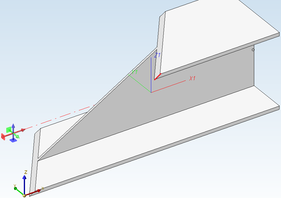
In this area you can choose between an export of the View angle or the Machine angle.
If you choose View angle, the angle between the local X-axis and the section line of top surface and lateral surface of the beam will be output. (red dash-dotted line in the image below).
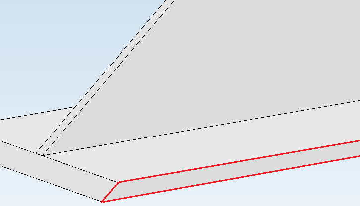
If you select Machine angle, the "lateral" angle between the top surface and the base surface of the beam will be output (highlighted in red in the image below). This setting is of importance for diagonally cut beams, as these beams have angle dimensions with different values.
Thread description
Here you specify how the Thread description is to be interpreted:
- in the form of a Pitch,
- With cole hole or
- Without core hole.
The Pitch option makes sense if you use the machine type Camprox.
Name of NCX file / DXF cross-section file
Here you can specify whether
- the Order number or Drawing number + Item number or
- Only item number
is to be used for the name of the NCX file.
You have the additional From FTD file option to use the parameters for name assignment set in the system file NCW_Dateibezeichnung.ftd.
Die NCX-Schnittstelle legt dann für jedes Teil eine NC-Datei mit der Dateinamenserweiterung .NCW und für Profile zusätzlich eine DXF-Datei mit dem Querschnitt des Profils an.
The name configuration will be omitted if you activate the Write all parts into one file checkbox, instead of creating one file for each itemized part.
In this case, you only need to select the automatically generated Name of DXF cross-section file (beam designation):
- Cross-section designation + Item number
- Only cross-section designation
- Only item number
- From FTD file
If you choose the From FTD file option, the name will be created as set in the system file NCW_Profilbezeichnung.ftd. Here it is important that attributes defined in the FTD file have been appropriately assigned in the drawing for export.
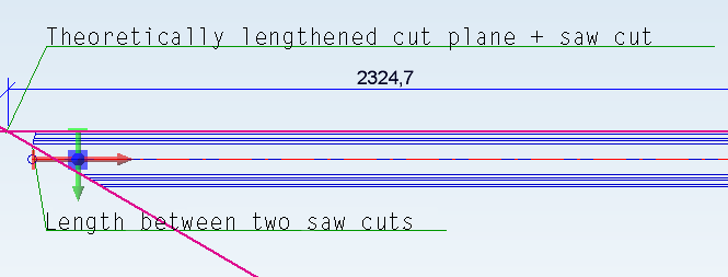
Cut planes
If two cut planes exist on the beam, you have the following two export options:
- Theoretical lengthening of two cut planes + saw cut
Here, one cut plane will be theoretically lengthened and the beam will be exported with this length and one saw cut, cutting off a piece of the beam. - Two saw cuts with two cut planes
The beam will be exported with its actual length, without diagonal cut and with both cuts as saw cuts.
The image below shows the difference:
If the option Directly indicate cut angles for flat steels is deactivated cut angles are initially exported in 90° and the deviating real cut angle has been realized as saw cut afterwards. If the option is active, cut angles of flat steels are exported analogously to beams.
Further options
|
Output itemized series beams as one part |
If you activate this checkbox, series beams that are sub-parts to the assembly will (if an itemization has been carried out beforehand) not be exported individually, but output as one single part. |
|
Comments |
If you deactivate this checkbox, the output of comments in the lines of the NCX file will be suppressed. This can make sense in particular cases, e.g. if the software used for the import of the files cannot read comments (e.g. UNLINK). |

DTSV Product Interface • DSTV BOM Interface • Steel Engineering Interfaces