Project: HiCAD P+ID
P+ID > Pipeline Symbol > Edit pipeline symbol ![]()
This function enables you to edit pipeline symbol data. You simply select a pipe connection belonging to the pipeline or one of the symbols (e.g. valve) assigned to it.
You can even edit a pipeline symbol that does not exist on the current drawing sheet, but to which pipeline parts or pipeline info symbols have been subordinated on the current sheet. To do this, edit the subordinated parts.
HiCAD then displays a mask enabling you to edit the symbol. Pipeline symbols can be edited in the same way as other symbols.
 Please note:
The code of a pipeline symbol is based on the pipeline number, the nominal width and the pipe class designation. In this case the nominal diameter is always expressed in mm.

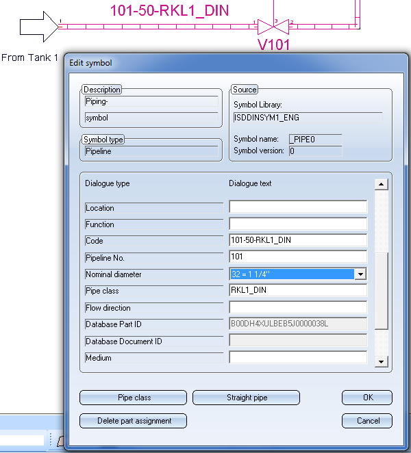
The dialogue for the editing of pipeline symbols looks as follows (if a pipe class has been assigned to the symbol):
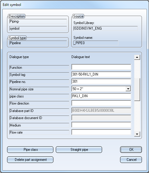
If you click Straight pipe, you can assign, in addition to the pipe class, a straight pipe from this pipe class to the symbol. The HELiOS mask for part search will only appear if more than one straight pipe with the preset nominal diameter exists in the pipe class.
A corresponding entry in the (previously empty) Database document ID input field indicates that a straight pipe has been assigned. If you now click on Straight pipe, the data of the assigned pipe will be displayed.
To remove the assignment of the straight pipe, click Delete part assignment. However, the assignment will not be removed until you click Delete part assignment a second time.
The assignment of a straight pipe makes sense if you want to use only pipe segments (and/or fittings with corresponding properties) for the pipeline that match this part. The attributes of the straight pipe (such as outer diameter, wall thickness, material) will then apply to the entire pipeline.
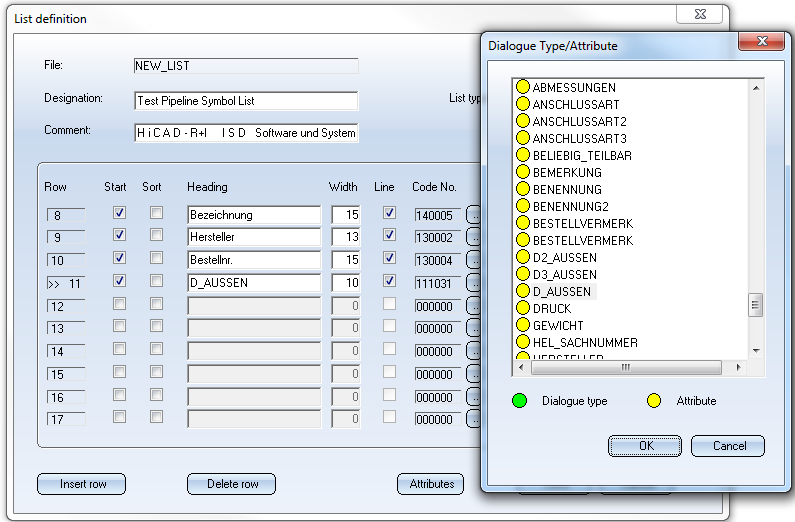
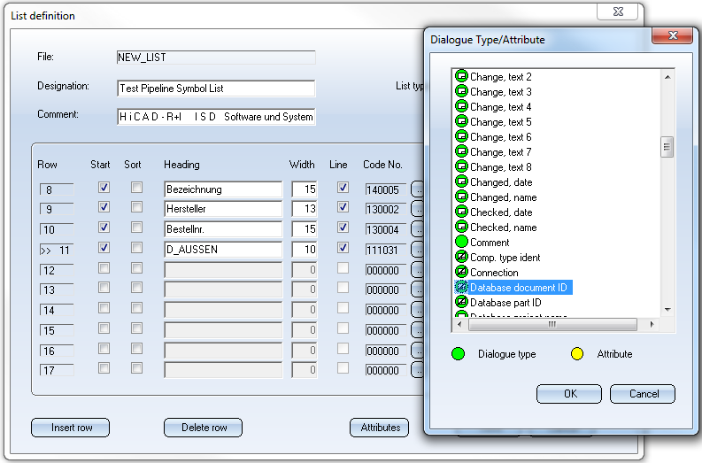
You can access these attributes when you generate a pipeline symbol list. A list definition that defines the outer diameter as a column may, for instance, look as follows:
 Important:
The dialogue type Database Document ID (81) needs to be contained in the list definition.
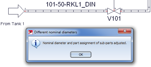
You have the option to change the nominal diameter of a pipeline in the P+ID, even if it pipeline parts have been subordinated to it by means of a part assignment. When changing the nominal diameter, existing part assignments of subordinated pipeline parts will be adjusted accordingly; this will be indicated by a corresponding message. If more that one matching part will be found, one of these part needs to be selected.
An example:
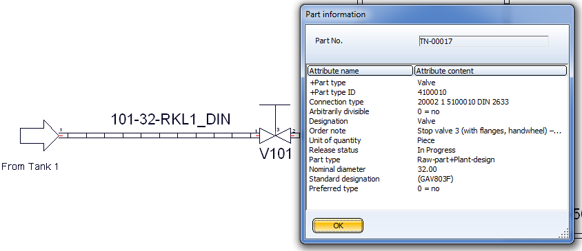
The part data of the valve with the code V101 before the nominal diameter change of the superordinate pipeline:
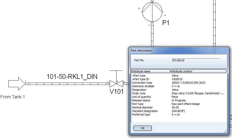
Change the nominal diameter of the superordinate pipe part with the code 101-50-RKL1_DIN from 50 to 32:
After confirming with OK, the following dialogue window appears:
Click OK to confirm the part data of the valve with the code V101:
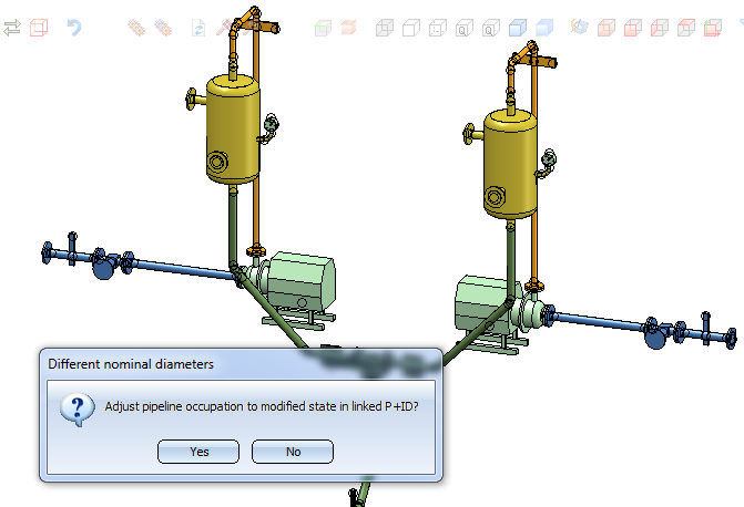
When you now switch to the 3-D layout plan with the Assigned 3-D layout plan ![]() function, the assigned pipeline will be exchanges after confirming the security prompt with Yes.
function, the assigned pipeline will be exchanges after confirming the security prompt with Yes.

|
© Copyright 1994-2020, ISD Software und Systeme GmbH |
Data protection • Terms and Conditions • Cookies • Contact • Legal notes and Disclaimer