Project: HiCAD Metal Engineering
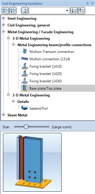
"Civil Engineering functions" docking window > Metal Engineering/Facade Engineering> 3-D Metal Engineering > Metal Engineering beam/profile connections > Base plate/Top plate
This Design Variant enables you to add a base or top plate connection to a series profile with only a few mouse clicks - complete with its associated individual parts and processings.
A prerequisite for this is that a suitable profile already exists in the current drawing.
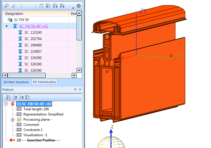
After selecting the function in the Civil Engineering functions docking window, identify the target profile for the connection with a mouse click in the drawing.
If possible, identify the profile near the end to which you want to attach the base plate or top plate. Whether you want to attach a base plate or a top plate can later be can later be specified via the Type of use in the insertion dialogue.
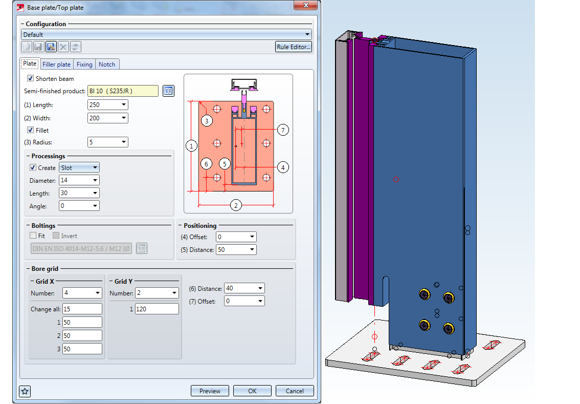
The Base plate/Top plate dialogue window with its various tabs - Plate, Filler plate, Fixing and Notch - will then be displayed.
Click the same-named button to see a Preview of the base plate with the settings you specified in the dialogue.
Favourites
The settings in the dialogue window can be saved as Favourites and reused at any time. To do this, click on the  at the bottom left of the window to activate the context menu. More about Favourites management can be found in the Manage Favourites topics of the HiCAD Basics Help.

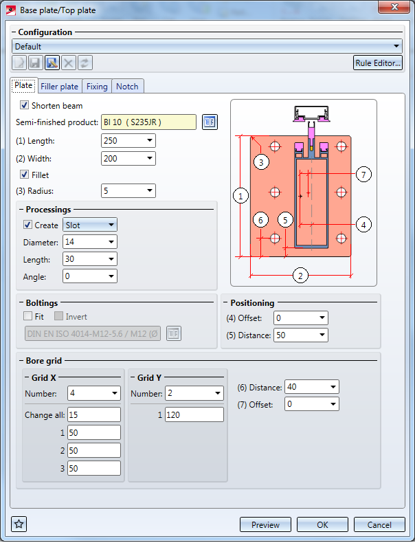
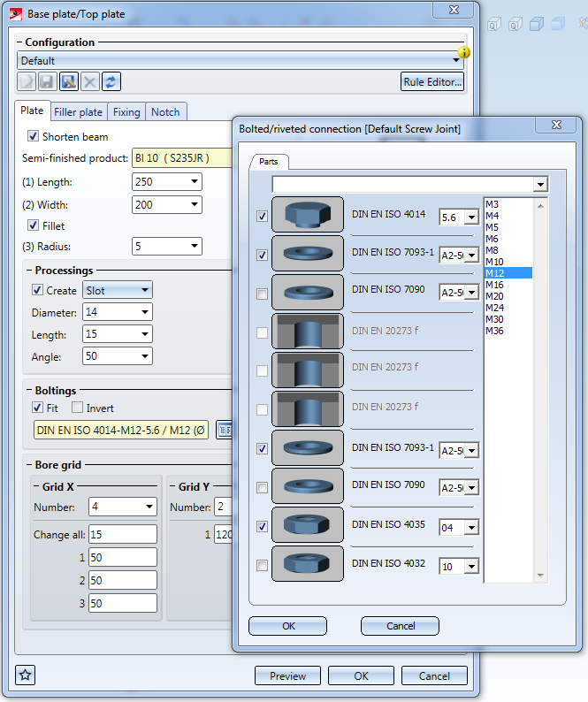
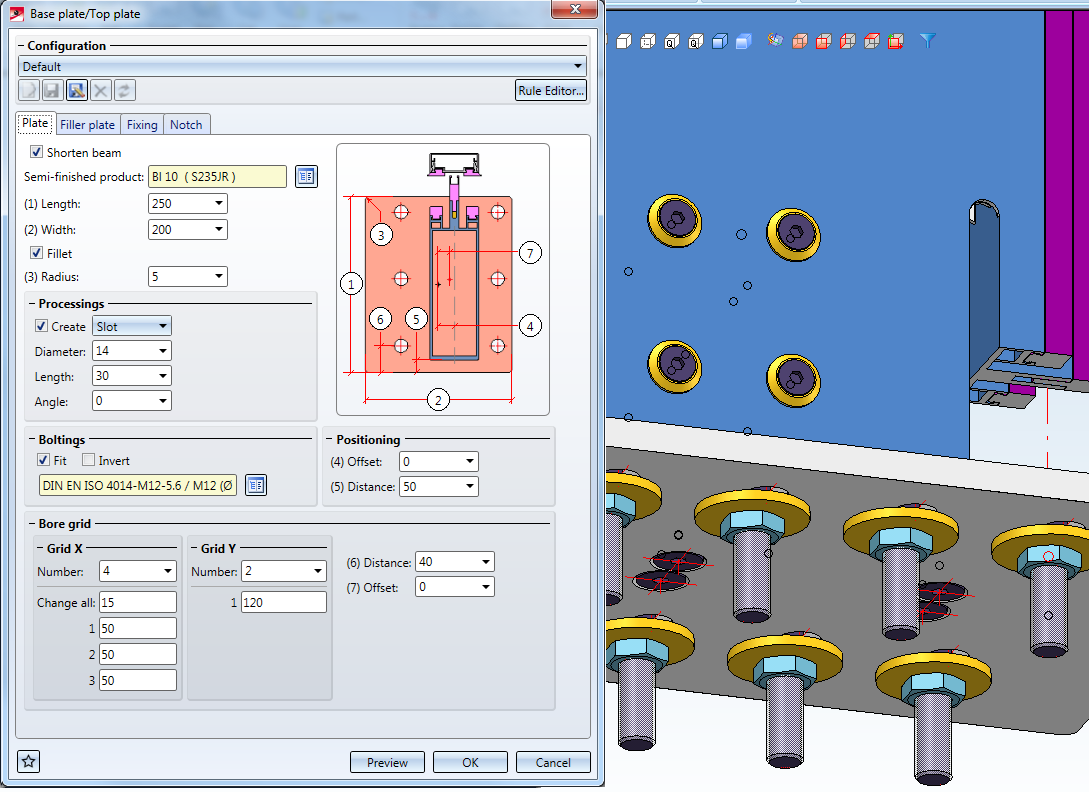
On the Plate tab of the dialogue window you can specify various properties of the base plate or top plate.
If you activate the Shorten beam checkbox, the profile will be shortened by the thickness of the base/top plate, so that the total length of the assembly including the plate corresponds to that of the original profile. If you deactivate the checkbox, the length of the profile will remain unchanged and the plate will be attached to its top or bottom, thus increasing the length of the assembly by the thickness of the plate.
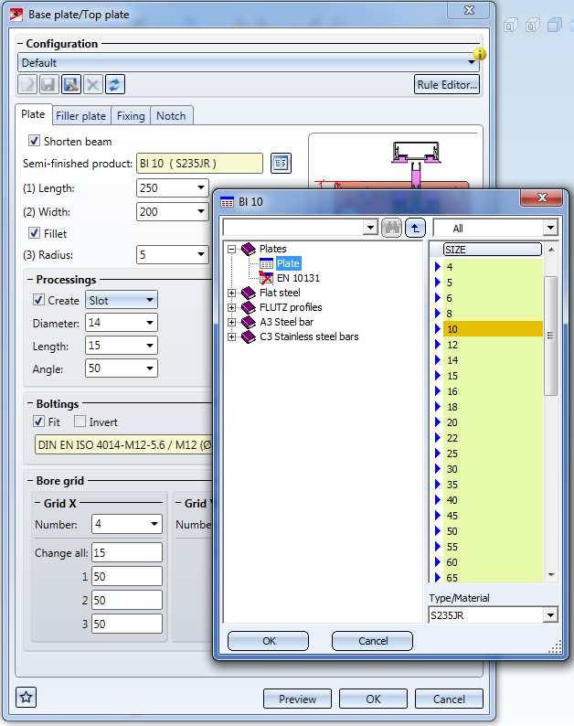
Further down you can select a Semi-finished product from the catalogue for the plate by clicking the icon to the right of the input field (e.g. a Wide flat steel instead of the default plate).
The miniature image at the top right of the window shows, by means of numerical annotations, the dimensions that can be assigned in the dialogue.
Via (1) Length and (2) Width you can change dimensions of the plate according to your requirements.
If you require filleted corner edges, activate the Fillet checkbox and enter a (3) Radius value for the fillet. If you deactivate the checkbox, no fillets will be applied.
The values for Positioning specify the position of the plate in relation to the profile, if you do not want the plate to be in centred position.
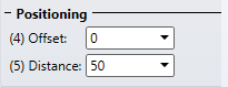
The (4) Offset value describes the position of the plate from its centre to the beam axis. If you enter a value here, the plate will be moved by this value to the right. If the value is negative, it will be moved to the left, accordingly.
The (5) Distance value describes the distance between the lower inner edge of the plate and the outer edge of the profile. If the value is 0, the edge of the profile contacts the edge of the plate. If you enter a negative value, the plate will be positioned in opposite direction.
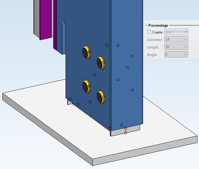
The other options concern the Processings on the plate.
If you deactivate the Create checkbox, no processings will be applied to the plate.
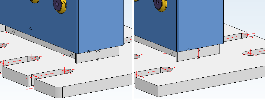
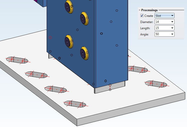
If the checkbox is activated (default) you can choose whether you want to apply Slots or Bores.
For Bores you can specify a Diameter, for Slots you can additionally specify a Length and an Angle.
Beneath Boltings you can select the individual components of the bolting from the HiCAD catalogue.
If you activate the Invert checkbox, the bolting will be inserted from bottom to top, and not from top to bottom as usual.
Further down, you have various options to modify the Bore grid.
The (6) Distance is calculated between the outer edge of the plate and the first bore row.
The (7) Offset of the bore grid will be calculated from the centre of the plate and the centre of the bore grid.
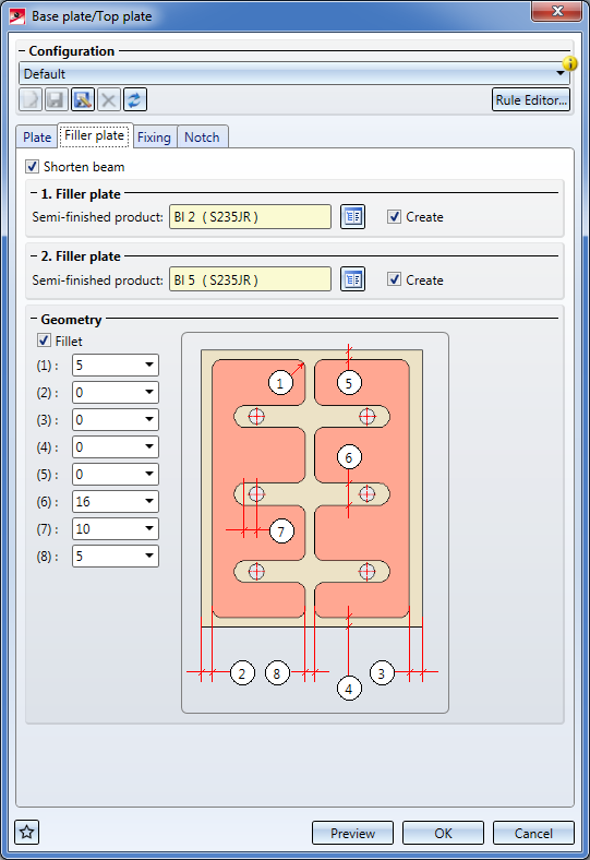
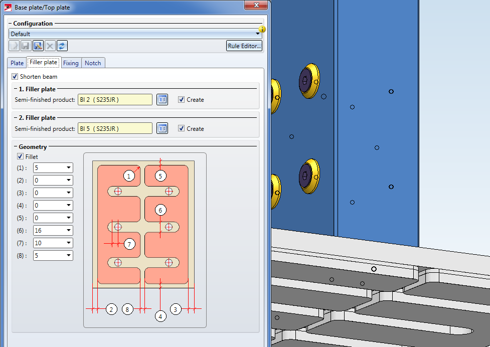
If you want to place a Filler plate under the Plate, open the same-named tab and specify the required parameters.
You can define up to 2 filler plates in the dialogue window - activate the checkbox of the filler plate that you want to define.
The corresponding Semi-finished product can be selected from the catalogue.
In the Geometry area of the dialogue you can (as with the Plate) specify fillets for the filler plates: Activate the Fillet checkbox and enter a radius in the input field (1).
The values below are distance values for the filler plate geometry according to the miniature image in the dialogue window:
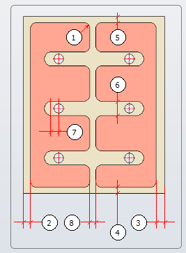
(2), (3), (4) and (5) are values for the distances of the Filler plate to the outer edges of the Plate, (6) is, so to speak, the diameter value for the gaps, (7) is the distance of the inner fillet to the bore row of the grid, and (8) the distance of the two filler plate halves to each other.
If a configuration via value is not possible, the Preview and the OK button will be greyed out until "realistic" values are set.
When you insert two filler plates, all values will always apply for both of them.
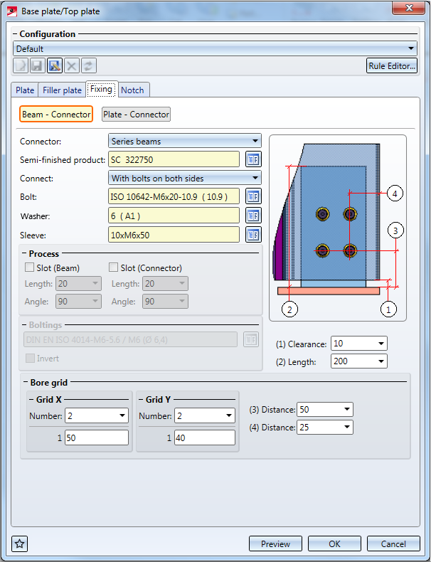
The Fixing tab contains 2 sub-menus: Beam - Connector and Plate - Connector.
In the Beam - Connector sub-menu you can define the connection between the profile ("beam") and the connector profile ("connector").
In the Plate - Connector menu you can define the connection between the connector profile and the plate.
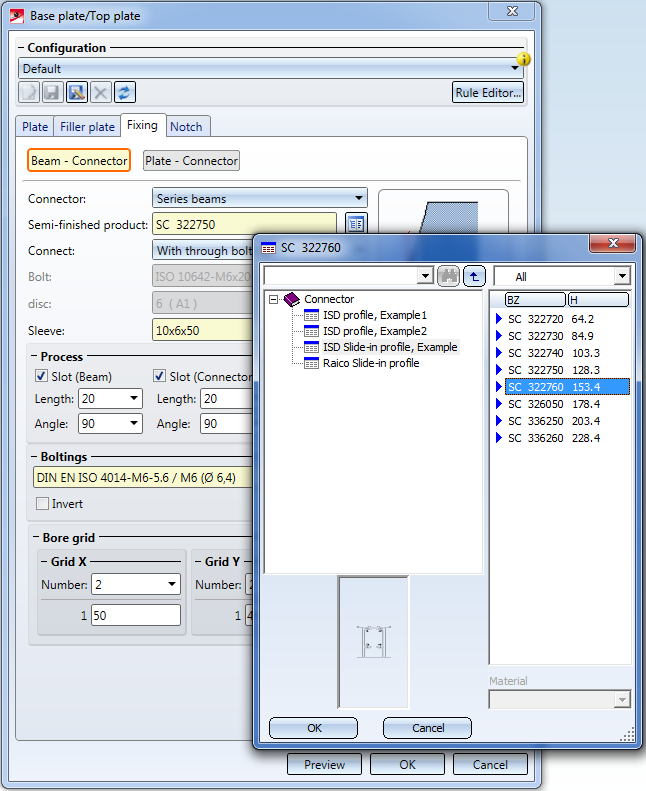
In the Connector selection box you can choose the type of the connecting profile. You can either select a Hollow profile or a Series beam, and select a Semi-finished product via the catalogue in the field below.
In the Connect field you can select whether the connection of the profiles is to be created With bolts on both sides or With through bolting.
For connections with bolts on both sides, threaded sleeves will be inserted. You can select the type of the Bolt, the Washer and the Sleeve from the catalogue. When you select different bolts, the washers and sleeves will be adjusted automatically. You can also assign a different material (if available) to the parts via the catalogue.
If a through bolting was selected, the first two fields will be greyed out, and only the Sleeve can be changed. Further down, beneath Boltings (greyed out if the option with bolts on both sided was selected) you can select the through bolting via the catalogue. Activate the Invert checkbox to change the direction of the bolting.
Beneath Process you can change the Length and the Angle of the slots on the Beam and the Connector. Further down you can find a Bore grid menu where you can change the Number of bores and the Distance between them.
The (1) Clearance value in the dialogue window defines the distance between the base plate and the profile, the (2) Length value is the length of the connector profile starting from the base plate.
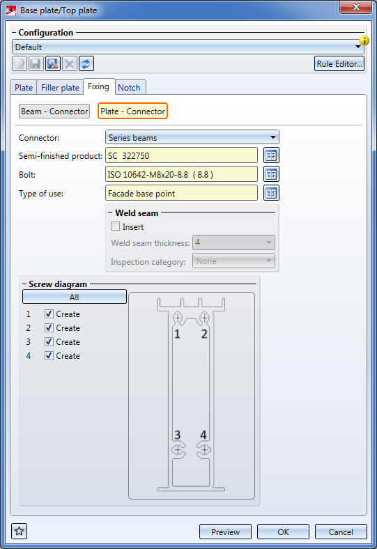
In the Plate - Connector sub-menu you define the connection between base plates and connector profiles.
The Connector and Semi-finished product input fields contain the connector profile that has already been selected and connected to the beam in the Beam - Connector sub-menu.
In the Bolt field you can change, via selection from the catalogue, the type of the bolt with which the connector profile is mounted to the plate...
...unless you activate the Insert checkbox beneath Weld seam (some connector profiles can only be welded, but not bolted). In this case, all options for bolts will be greyed out. Instead, you can enter a value for the Weld seam thickness and, if desired, also select an Inspection category beneath Weld seam.
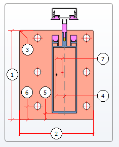
If the connection is created with bolts or screws, you can select beneath Screw pattern whether All bolts should be set for the spots intended for boltings on the profile, or if you want to omit some of them, by activating or deactivating the corresponding Create checkboxes. The miniature image on the right shows the positions of the bolts on the profile.
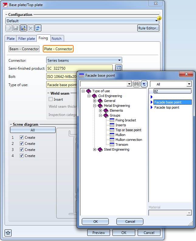
Furthermore, you can assign a Type of use here in order to identify the plate as a Base plate or a Top plate.
The Type of use will be assigned after clicking the OK button in the dialogue window. As long as you work with the Preview option to view changes, you can still change the Type of use; after clicking OK, you can still change the Type of use; after clicking OK is will be set and can no longer be changed.
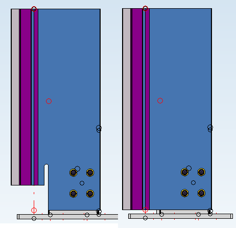
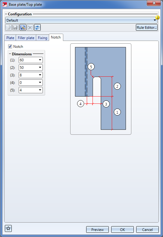
On the Notch tab you can specify, by activating or deactivating the same-named checkbox, whether the profile to which the base plate is attached, is to be notched or not.
If the profile is notched, the Dimensions values can be set as desired. (1) to (4) are distance values according to the miniature image in the dialogue window, (5) determines the radius.
 Please note:
When working with the 3-D Metal Engineering connections, please also read the notes on

Connections / Design Variants (ME)
|
© Copyright 1994-2020, ISD Software und Systeme GmbH |
Data protection • Terms and Conditions • Cookies • Contact • Legal notes and Disclaimer