Project: HiCAD Metal Engineering
"Civil Engineering functions" docking window > Metal Engineering/Facade Engineering> 3-D Metal Engineering > Metal Engineering beam/profile connections >Mullion-Transom connection
In the Civil Engineering functions docking window (on the right hand side of the HiCAD window) you can find the Metal Engineering / Facade Engineering entry. Here you will find all Design Variants that are available for Metal Engineering.
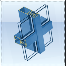
This sub-entry contains, among other design variants, a pre-defined Mullion-Transom connection, which is in fact a versatile 3-D Metal Engineering Schüco FW50/60 connection .
After selecting the connection, you first need to click the profile that you want to connect, and then the target profile to which you want to connect the first profile.
The dialogue window opens, enabling you to define your exact configuration.
Favourites
The settings in the dialogue window can be saved as Favourites and reused at any time. To do this, click on the  at the bottom left of the window to activate the context menu. More about Favourites management can be found in the Manage Favourites topics of the HiCAD Basics Help.
In the Geometry area, you can specify values for the distance lengths, which are identified by corresponding letters in the graphics window on the right hand side of the dialogue.
|
S1 |
Clearance between mullions and transoms |
|
S2 |
Clearance between the cover strips |
|
M |
Clearance between mullion axis and transom insertion depth (start) |
|
B |
Width of slot in transom |
|
L |
Length of slot in transom |
|
D |
Diameter of bore in mullion (for |
If you want to Create additional bores (for additional slots in the transom, or additional bores in the mullion for the mounting of slip-in transom profiles), activate the corresponding checkbox. The dialogue will then be expanded accordingly:

Configuration dialogue for 3-D Metal Engineering connection with additional bores
Beneath Grid X and Grid Y (X- and Y-direction of the grid in top view of the bores) you can specify the Number of bores.
In the input field below you can assign the distances between the bores either individually (the corresponding number of input fields will be displayed for the previously selected number of bores), or, in case of identical distances, use the Change all field to set all bores at once.
In the Calculation method field you can select between option 1 and 2: If you choose procedure 1, the sketch edge runs parallel to the axis of the part, if you choose procedure 2, the sketch edge runs vertical to the part, as can be seen in the screenshot below:

Left Connection according to Calculation method 1; Right: Connection according to Calculation method 2
The Accessories list at the bottom of the dialogue shows which parts and processings that are not displayed in the drawing belong in the BOM of the part. To add further parts, click +, and then click  to select the desired parts from the catalogue. Use the "Minus" sign to remove parts from the list.
At in the Configuration area the top of the window you can save a configuration for a later reuse, or load an already existing configuration.
 Please note:


Connections / Design Variants (ME)
|
© Copyright 1994-2020, ISD Software und Systeme GmbH |
Data protection • Terms and Conditions • Cookies • Contact • Legal notes and Disclaimer
