Example of a Design Variant with Blind Hole and Thread
Step 1: Create Construction
- Create a cuboid (name: Processed Part) and create a processing plane.
- Then insert a blind hole and a thread (Free Hole, Point Angle 180°).
- Generate a dummy part (name: Design Variant_Base Part) using the Dummy 3-D Part function from the New menu.
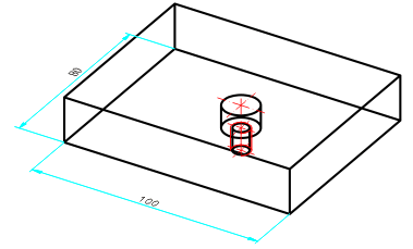
Example: Cuboid with blind hole and thread
Step 2: Create Design Variant base body
- Move the part "Processed Part" in the ICN under the dummy part.
- Activate the dummy part.
Now define the dummy part for the variant base.
- Right-click in the (empty) dummy part's feature log. Then activate Design variant base body: No (No or Yes always represents the current state. Clicking changes the state.)
The dummy part is only used as the basis for the design variant in the drawing in which the variant is generated. It is used there, for example, to include the variant's parameter variables. It does not feature in the drawing in which the variant is fitted.
Step 3: Create the Part's Variables
The design variant base body's variables become the design variant's parameters. In other words, the system prompts for these variables when the variant is fitted. If the variables have a comment, it is displayed instead of the variable name during the prompt.
- Next, activate the dummy part (Design Variant base part).
The variables need to be created in the dummy part for the design variant.
- Right-click in the dummy part's (empty) feature log. Activate the Parameter variables of variant function.
- In the variant table, use the right mouse button to activate the Add new variable function. Then, choose Element > Point and enter, say, p1.
The system then prompts for a point.
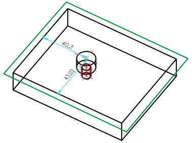
- Identify a fitting point in the drawing.
- Specify further variables for, say, the blind hole.
Now assign the variables to the elements.
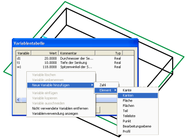
Variables table
- Activate the part "Processed Part" in the ICN. In the feature log below the blind hole, use the right mouse button to select the Point entry and activate the Edit formula function.
- Enter the variable name p1 here, instead of the dimensions, and proceed in the same way with the other variables.
Variants for insertion point, diameter, blind hole depth and point angle
- In the feature log below the blind hole, use the right mouse button to activate the processing plane and choose the Edit formula function.
- Enter active_coor() into the entry mask.
This entry aligns the design variant to the active processing plane during insertion. You do not need to make an entry in the variable table, as there is no prompt during fitting.
For a list of all formulas, see the chapter entitled Feature Parameter Formulas.
Step 4: Marking the Part as the Starting Point for Processing within the Design Variant
On the one hand, design variants can process one or more parts of the drawing in which they are used and, on the other hand, also introduce new parts into the drawing. The formula entered for the generation feature of the part indicates how to proceed with which sub-part of the design variant base body:
Formula for the Processed part: All features apart from the generation feature (in this case, the cuboid) are attached to the log of the part in the fitting drawing. The formula determines which part in the fitting drawing.
Formula for assembly: During fitting, the part becomes a sub-part of the part specified in the formula.
- Activate the part Processed part. In the feature log, use the right mouse button to choose the Formula for processed part function.
- Enter active_part() and choose OK to exit the entry mask.
Step 5: Create Design Variant
- Activate the dummy part Processed part and, in the feature log, use the right mouse button to choose the Create design variant function.
- Enter an * and a name (no more than 27 characters) for the design variant in Explorer.
The extension for the design variant is FMV (Feature Modifying Variant). As, internally, it is a part that is saved, as was the case with the previous feature variants, the files <name>.FMV.KRP, <name>.FMV.KRP.FEA etc. also exist, in addition to <name>.FMV.
Step 6: Insert Design Variant
- Create a new drawing with a solid primitive and a processing plane.
- Activate the context menu of the Solid primitive > Insert > Main Part/Variant > Via Explorer.
- In Explorer, select the design variant with the extension <name>.FMV and specify the variables and the fitting point.
The system prompts for the variables in turn (alphabetically). This example requires you to specify a fitting point to position the blind hole with thread. The design variant is then inserted.
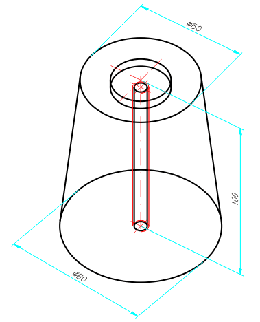
Example of the inserted Design Variant after assigning of formulas
The Design Variant feature step is produced in the log. Special sub-points for the design variant are:
- Variables table
Opens a variable table containing the variant's parameter variables.
- Log
If you expand the entry, you will see the log for the design variant. In particular, the log may contain errors which have occurred during fitting.

