Project: HiCAD Element installation
Example: Create Parts with Connection Parameters - Step 2
Step 2: Create variant for sub-structure
The topic Create Own Profiles For Sub-structures explains in detail how to create your own beams/ profiles for sub-structures. Therefore, only the basic steps will be listed here.
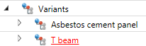
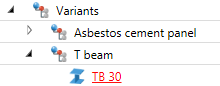
- In the Variants assembly, create a sub-assembly called T-beam.
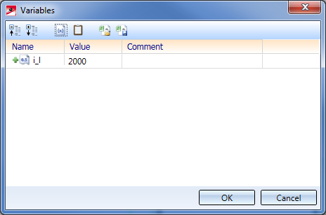
- Right-click the assembly in the ICN and choose Properties > Part variables.
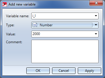
- Create a new variable. Name:
i_l, Type: Number, Value:2000.
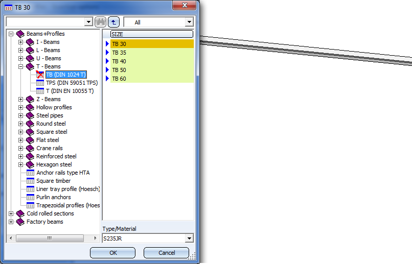
- Choose the function Steel Engineering > New > Insert new standard beam. Insert a T-beam of the type TB 30 with a length of your choice in your drawing.
- In the ICN, move the T-beam into the assembly T-beam.
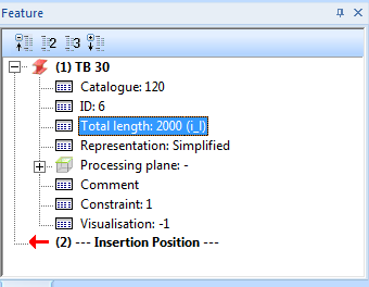
- In the Feature window of the ICN, expand the Feature log entry TB 30 and double-click the Total length entry. Enter
length as the new value.
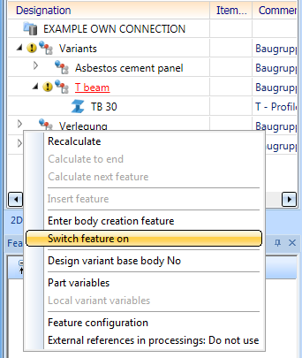
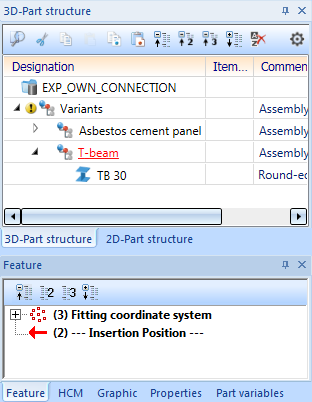
- Select the assembly T-beam. As there is no Feature log for this assembly yet, you need to activate it: Right-click on the empty Feature window of the ICN and choose Switch feature on.
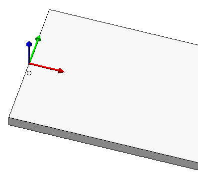
- Then, choose Drawing > Others > World CS
 > Define Fitting CS and identify, one after the other, the following points in the top view of the upper side of the beam:
- the mid point on the left edge,
- the mid point on the right edge, ,
- the point in the top left corner.
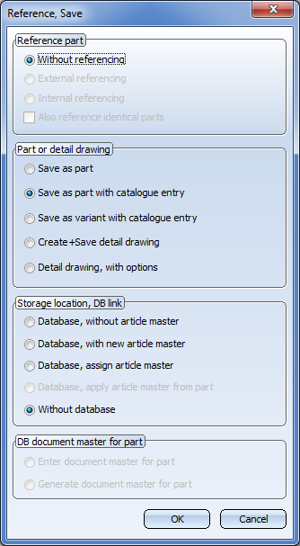
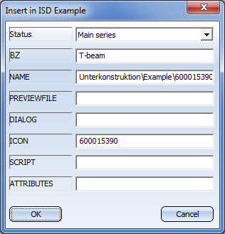
- The T-beam is now prepared for saving to the catalogue for the element installation. Select the assembly T-beam and choose the function Drawing > Save/Reference > Reference part, Save, Detail drawing. In the displayed dialogue window, choose the settings Without referencing, Save as part with catalogue entry and Without database..
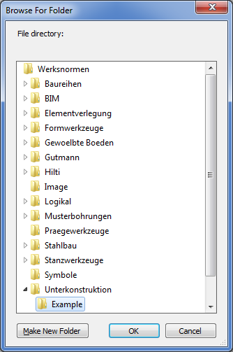
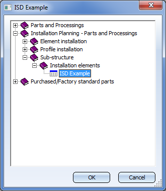
- Choose the data directory Werksnormen\Unterkonstruktion\Example and the catalogue Installation planning - Parts and Processings > Sub-structure > Installation elements > ISD Example. The settings that will then be displayed can be applied as they are; no Bitmap creation will be required here.
Next step: Insert and Link Element Installation and Sub-structure


Connection Parameters
|
© Copyright 1994-2020, ISD Software und Systeme GmbH
Version 2502 - HiCAD Element installation
Date: 27/09/2020 Language: 1033
|
> Feedback on this topic
|
• • • •