Column
Meaning
Unambiguous data record number, automatically assigned by the Catalogue Editor.
Automatically set
You can assign a particular status to each data record. This status affects the choice of parts in HiCAD.
You can choose between the following statuses:
- Not available
The data record is greyed out in HiCAD and cannot be chosen. - Main series
These data records have first priority for the insertion in HiCAD. - Sub-series
These data records have second priority for the insertion in HiCAD.
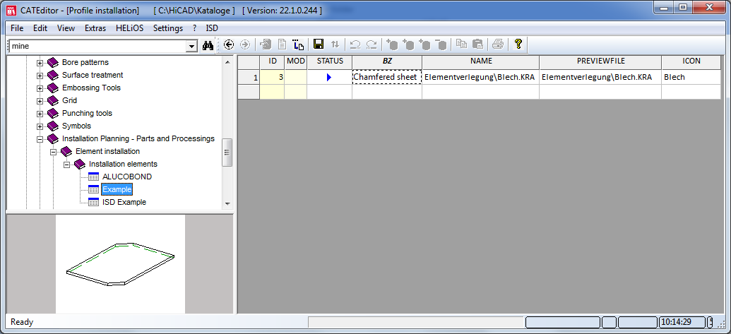
BZ
Designation of the installation element
NAME
Link to the KRA file of the installation element, relative to the HiCAD folder Kataloge\Werksnormen.
Examples:
- The entry test.KRA refers to the HiCAD folder Kataloge\Werksnormen\test.KRA.
- The entry test\test.KRA refers to the HiCAD folder Kataloge\Werksnormen\test\test.KRA.
DIALOG
Name of the ZIP file for customized dialogue windows (see Example)
PREVIEWFILE
If you want a simplified .KRA file to be displayed as a preview image for insertion, you can use (as with the NAME column) the name of this simplified .KRA file here.
The entry can also refer to the original .KRA file; especially in case of more complex installation elements, however, a simplified preview should be used for performance reasons.
If a preview image in the BMP or EMF format is to be assigned to a table, you can enter the name of the file here.
Extensive information of preview images can be found in the Help of the Catalogue Editor.
SCRIPT*
In the SCRIPT field you can enter a reference to a scripts enabling you to choose between different levels of detail of the variant. For further information on this topic, please contact our Consulting team.
ATTRIBUTES*
The ATTRIBUTES field is only required if the profile is created via a variant, with a feature script which changes attributes of a part. In this case, the names of the changed attributes must be entered in this field, separated by semicolons.
For installation elements, conditions can be assigned for the utilized variables. In addition, error messages can be defined that are displayed if the conditions for the insertion of the element are not fulfilled. In this case the respective input field or the OK button will be marked with the  or
or  symbol. When you move the cursor over these symbols, the corresponding error message will be shown.
The conditions and error messages for the variables must be stored in a file the name of which must be entered in the CONDITIONS column.
More information on conditions and error messages can be found in the topic Customizing the Dialogue Window.
GAPMODE*
The clearance can be preset in the appropriate catalogue table. When choosing the corresponding installation element in the Element installation dialogue, the clearance will be set to this value.
The pre-setting of the clearance takes place via the table columns
- GAPMODE and
- GAPDEFAULT.
You enter the required value for the clearance in the GAPDEFAULT column. If you want to activate this value as the default value, set the column GAPMODE to 1. When choosing the corresponding element in HiCAD for the element installation the value for the clearance will be automatically set to the value entered in the GAPDEFAULT column.
To deactivate this pre-setting, set the column GAPMODE to 0.
The tables that are supplied with HiCAD already contain these columns.

GAPDEFAULT*