Project: HiCAD Element installation
In the dialogue window for the ALUCOBOND Tray panel SZ-20 (with accessories) you can find 3 tabs with setting options:
Further topics:
Please also note the Design Variant Flange for SZ-20.
Here you can choose the desired semi-fnished product and the parameters for Connection, top, Base point, Connection, left and Connection, right. Furthermore, you can choose here whether standard parts (for fastening) should be installed or not. The ISD default setting is that standard parts are created, i.e. the checkbox is active. If the checkbox is inactive, the standard parts are not listed in the bill of materials.
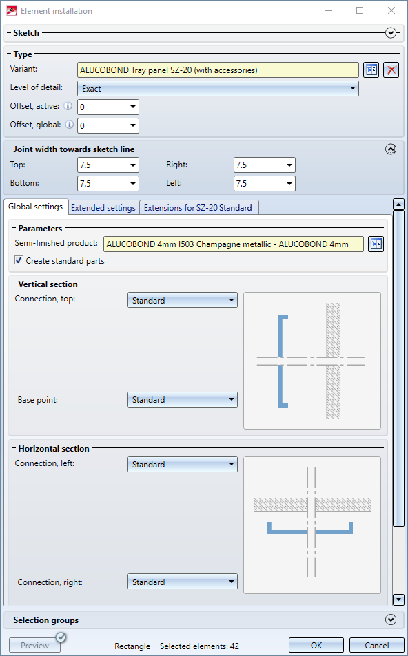
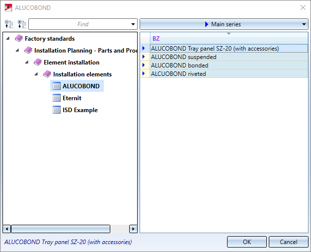
Selection of ALUCOBOND Semi-finished products:
Possible connection options:
|
Horizontal section |
|||
|
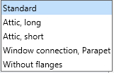
Top |
|
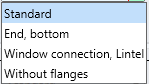
Base point |
|
|
Vertical section |
|||
|
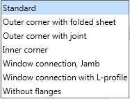
Left |
|
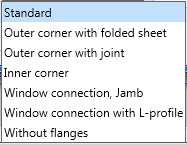
Right |
|
Depending on the chosen connection type, further input fields may be displayed.
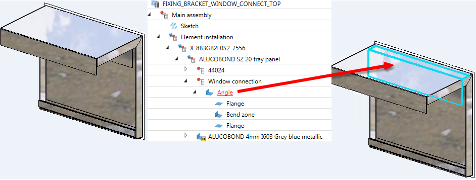
If you choose Connection, top: Window connection, parapet beneath Vertical section when installing ALUCOBOND®Tray panels SZ-20, an additional angular L-bracket will be used for the connection.
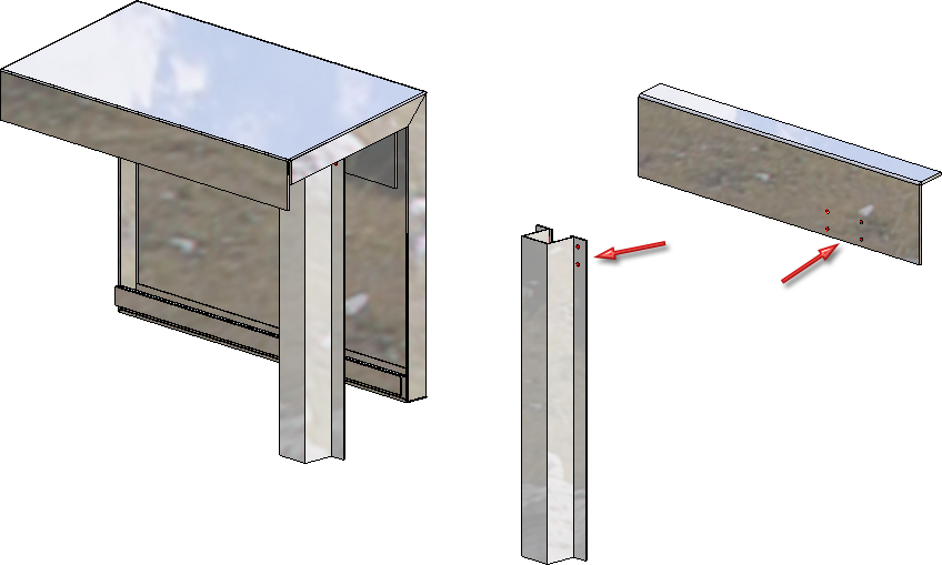
If you connect such an element installation with a sub-structure, the sub-structure will be shortened appropriately. Also, bores will be applied to the sub-structure and the fixing brackets.
If Connection top: Window connection has been selected for the vertical section, the connection can also be installed without flanges. To do this, simply enter the value 0 for Length of folded sheet.
The Attic connection can also be installed without the last flange by entering the value 0 for Length of folded sheet.
 When installing ALUCOBOND SZ-20 tray panels with window connection, the "L-profile" is no longer part of the panel since HiCAD 2020 SP2. Instead, it is only created by the connection with the sub-structure. It is designed as a "short piece" on each sub-structure and is not continuous.
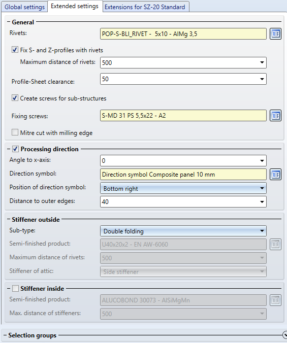
On this tab you specify the processing types for the suspension (S- and Z-)profiles and stiffeners.
If you want the S- and Z-profiles (suspension profiles) to be riveted to the panel, activate the corresponding checkbox and specify the maximum distance of the rivets.
You can determine whether the screws for the mounting of the substructure are to be created by activating or deactivating the corresponding checkbox.
If you want the mitre cut to be displayed with a milling edge, activate the same-named checkbox and specify then maximum distance of the rivet.
Stiffeners are always riveted to the plate.
Instead of the stiffener profiles at the edge you can also apply double foldings to the material. To do this, choose the Double folding option from the Sub-type selection box. Also, you can select a Direction symbol and specify the position of the symbol and the Distance to outer edges.
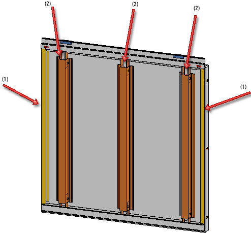
ALUCOBOND® tray panel - (1) Stiffener profiles at edges of panel; (2) Stiffener profiles on ("inside") panel
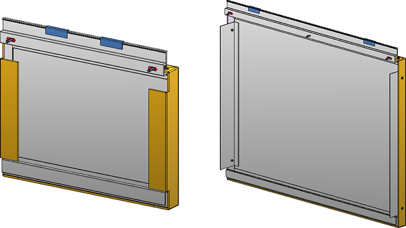
ALUCOBOND® Tray panel SZ 20 - Left: Double folding; Right: Window connection with L-profile
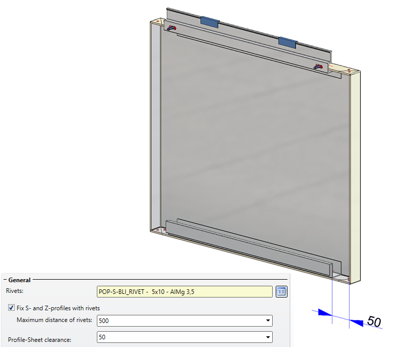
The length of S- and Z-profiles (suspension profiles) can be influenced by specifying a clearance between profile and sheet.
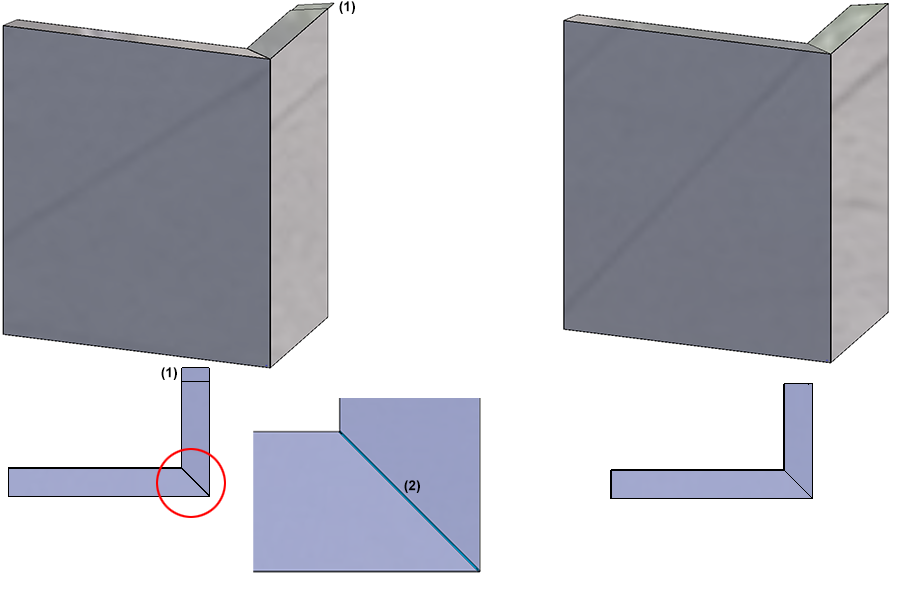
For attic connections, it is possible to lengthen the Stiffener outside to the attic and rivet it to the flanges. To do this, select the setting Stiffener of attic: Side stiffener.
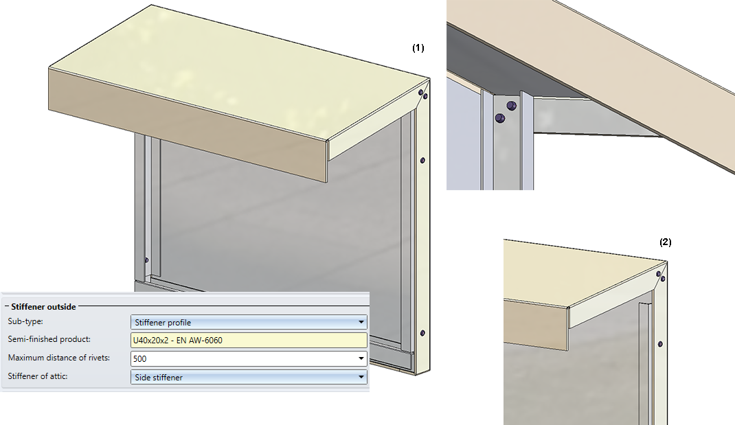
(1) Stiffener, lengthened up to the attic; (2) Stiffeners on attic = Corner sheet
Please note the following for ALUCOBOND® Tray panels SZ-20 - depending on the settings during insertion:
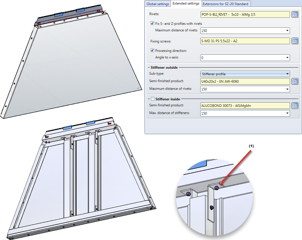
Example of a trapezoidal ALUCOBOND®Tray panel SZ-20, (1) No bores are created here!
On this tab you can specify the type of the lateral flanges for the connection types Attic, long / Attic, short. Also, you can specify here whether corner attics are to be created with or without clamping profile. Furthermore, you can specify the depth of the tray panel here.
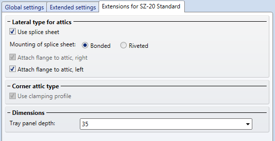
The connection between splice sheet and tray panel can be a bonded or a riveted one. The rivets will be inserted on one attic side only, at a 50 mm distance to the edge.
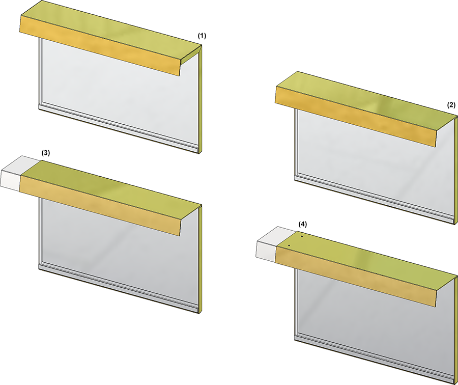
(1) Standard; (2) Without side flanges; (3) Splice sheet, bonded; (4) Splice sheet, riveted
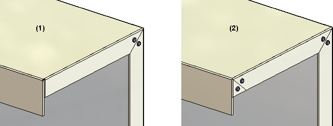
The image below shows a SZ-20 tray panel. Horizontal section: Connection, top. Attic, long; Vertical section: Connection, right. Outer corner with folded sheet. The left tray panel has been created with splice sheet and clamping profile, the right one without these elements.
(1) Splice sheet, (2) Corner attic with clamping profile
Attic connections can be created with or without lug:
(1) With lug; (2) Without lug
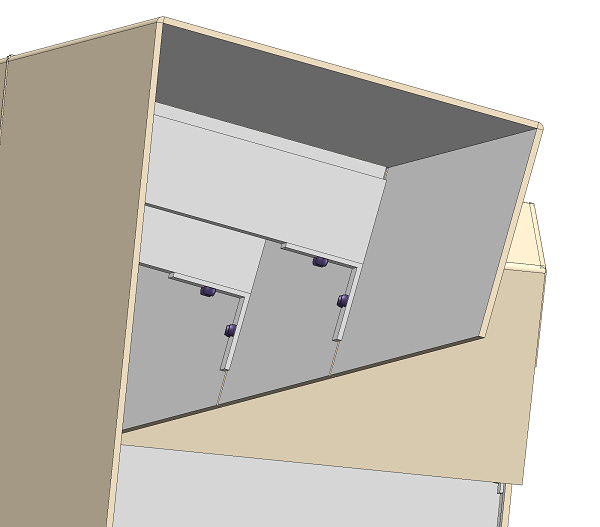
For SZ 20 element installations, a matching profile for a sub-structure is available.
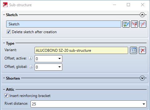
The option Install reinforcing bracket has an effect if the sub-structure is connected to an element installation via the Connection function, which contains elements with attic connection. In this case, the substructure is connected to the rear parapet bracket via angles and riveted:

Element Installation • Catalogue Editor
|
© Copyright 1994-2020, ISD Software und Systeme GmbH |
Data protection • Terms and Conditions • Cookies • Contact • Legal notes and Disclaimer