> Connecting sheet, Main part
Project: HiCAD Sheet Metal
Sheet Metal > New > FromSkt > Connecting sheet, Main part
Sheet Metal > New > FromSkt > Connecting sheet, Sub-part 
Use the Connecting sheet functions to connect two composite edges (guidelines) by a sheet. You can create the connecting sheet as a main part or as a sub-part. Proceed as follows:
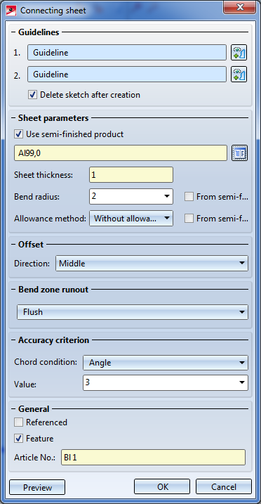
The dialogue window for connecting sheets appears.
If you want to identify a different composite edge, click the  icon in the Guidelines area. Identify the 1st or 2nd guideline.
Click the  icon to select the standard for the semi-finished product from the HiCAD Catalogue Editor. The selection of a semi-finished material does not only influence the sheet thickness, but also the also the bend radius, the allowance method and the article number. If the Semi-finished product checkbox is activated, the sheet thickness can no longer be changed, while bend radius, article number and allowance method still remain changeable. If you double-click the Connecting sheet feature, you can also activate or deactivate the Use-semi-finished product checkbox later if desired.
|
Centre |
The material thickness will be applied evenly to both sides of the composite edge. |
|
First side |
The material thickness will be applied to the "outer" side. |
|
Second side |
The material thickness will be applied to the "inner" side of the sketch. |
Click Preview to check your entries.
|
|
No special processing |
Bend zones converging in one corner of the sheet will be shortened to avoid overlaps. |
|
|
Flush |
If several bend zones converge in one corner of the sheet, the sheet corner will be expanded in such a way that there will be enough space for the bend zones. The front faces of the bend zones will be planar surfaces. They will not be adjusted to the adjacent flanges. |
|
|
Flush and corrected |
If several bend zones converge in one corner of the sheet, the sheet corner will be expanded, and the front faces of the bend zones will be adjusted to the neighbouring flanges. |
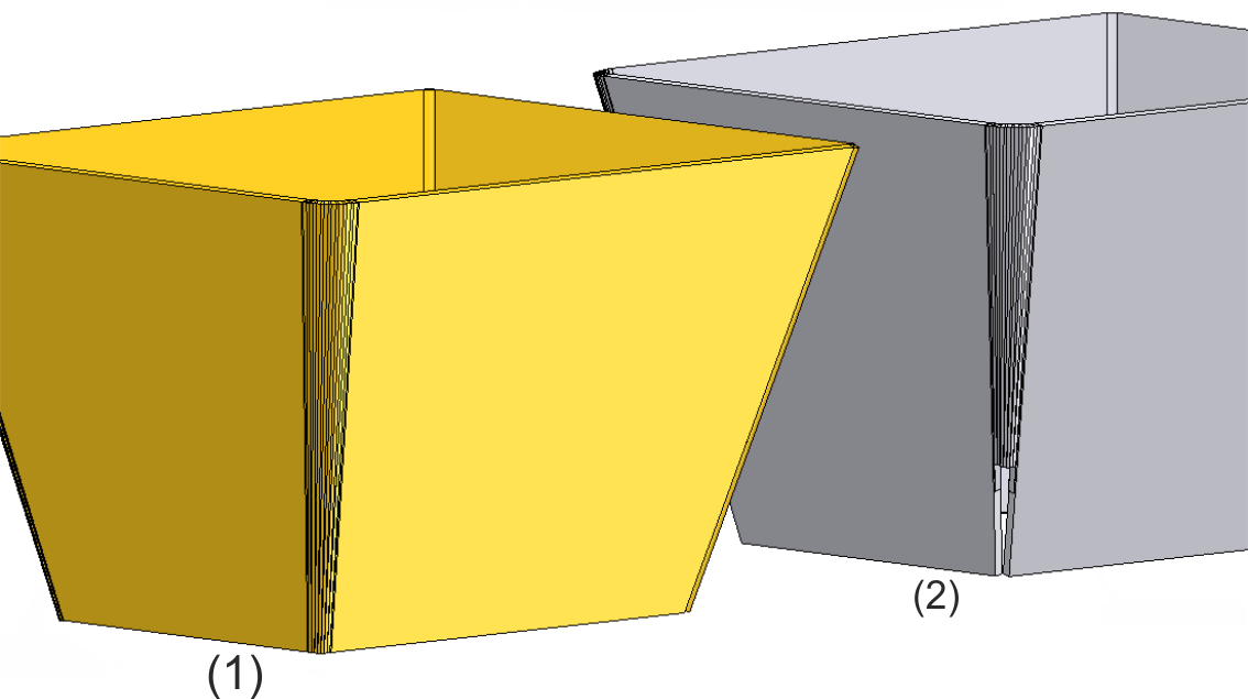
(1) Flush and corrected
(2) No special processing
The arcs of the composite edges (guidelines) will be approximated synchronously by polygon courses, so that two lines each lie in one plane, thus defining a flange. The accuracy of the resulting sheet flanges can be defined in the Accuracy criterion area.
|
|
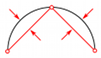
Angle |
The value determines the maximum angle in the corner between two flanges. The smaller the angle, the more accurate the approximation. |
|
|
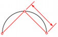
Distance |
The entered value determines the maximum distance between the flange and the composite edge (guideline). |
|
|
Length |
Here you enter the maximum width of a flange created by approximation in millimetres. |
Frequently used parts should be saved as referenced parts. The part will then be additionally saved as an individual part at the end of the process, and will not be integrated as a "fixed" part into the drawing. If any modifications are applied to the part, you can update the part in the drawing..
To switch off feature creation during the generation of this base sheet, deactivate the Create feature  checkbox. This checkbox is active
 ![]() by default.
by default.
If the Via catalogue checkbox beside Article No. has been activated ![]() while the Use semi-finished product checkbox is also active
while the Use semi-finished product checkbox is also active ![]() , the article number will be loaded from the catalogue. The catalogue column can be specified. If the Via catalogue checkbox beside Article No. has been deactivated
, the article number will be loaded from the catalogue. The catalogue column can be specified. If the Via catalogue checkbox beside Article No. has been deactivated ![]() you can enter any article number.
you can enter any article number.
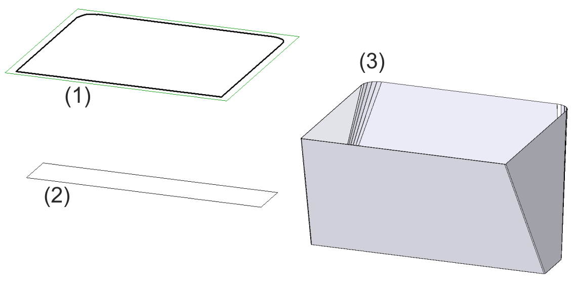
(1) 1st composite edge
(2) 2nd composite edge
(3) Connecting sheet (Accuracy criterion: Distance 3)


|
© Copyright 1994-2020, ISD Software und Systeme GmbH |
Data protection • Terms and Conditions • Cookies • Contact • Legal notes and Disclaimer