Project: HiCAD Sheet Metal
Sheet Metal > New > From 2D ![]()
This function in HiCAD enables you to generate a new 3-D sheet part from a 2-D contour. The complete 2-D contour must be located in one part. All closed contours are automatically adopted and bending edges are defined by you.
When data is being transferred from external systems (e.g. .DXF), HiCAD offers a correction attempt with the HCM in the event of imprecise contours.
The Sheet from 2-D development window opens.
If you decide to use a semi-finished product from the Catalogue Editor  , the he Sheet thickness and the Material will then be taken from the Catalogue Editor.
The Article number for the base sheet can, after activation of the Via catalogue  checkbox at the bottom of the dialogue, be taken from the Catalogue Editor. You determine in the Catalogue Editor which entry is to be taken over as Article number. If you have not activated the checkbox
 ![]() you can enter any Article number.
you can enter any Article number.
Semi-finished products can also be activated/deactivated or changed subsequently. To do this, double-click the Base sheet feature. The dialogue for base sheet creation will be opened. You can then activate or deactivate the Use semi-finished product checkbox, or click the  icon to choose a different semi-finished product. Click OK to confirm your changes and apply the changes.
Frequently used parts should be saved as referenced parts. The part will then be additionally saved as an individual part at the end of the process, and will not be integrated as a "fixed" part into the drawing. If any modifications are applied to the part, you can update the part in the drawing.
To switch off feature creation during the generation of this base sheet, deactivate the Create feature  checkbox. This checkbox is active
 ![]() by default.
by default.

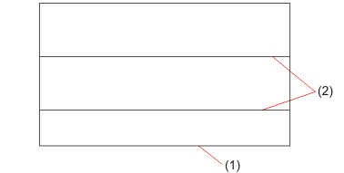
(1) 2-D polyline
(2) Bend zones
The Polylines selection menu opens after identification. You can take lines over individually if, for example, not all lines have been identified. You can also remove lines which you do not want to apply to the new sheet, e.g. subtractions and punches.
If you choose Execute, the sheet is generated immediately. If you choose Continue, the Bend zone dialogue opens.
The bend zones are marked.
If you decide that you do not want one of the bend zones to be taken over, deactivate it by choosing Remove.
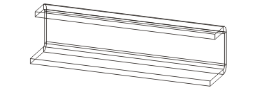
The sheet is constructed according to the entries made and created as a developed base sheet. If desired, use the Fold flange function to fold the flanges and bend zones.


|
© Copyright 1994-2020, ISD Software und Systeme GmbH |
Data protection • Terms and Conditions • Cookies • Contact • Legal notes and Disclaimer