Project: HiCAD Sheet Metal
Civil Engineering functions > Sheet Metal > Cam joint
In practice, so-called cam joints are used for a quick positioning and welding of sheets. The Cam joint Design Variant enables you to conveniently connect two base sheets with each other.
The base sheets must have a common intersection point in their lengthening. Proceed as follows.
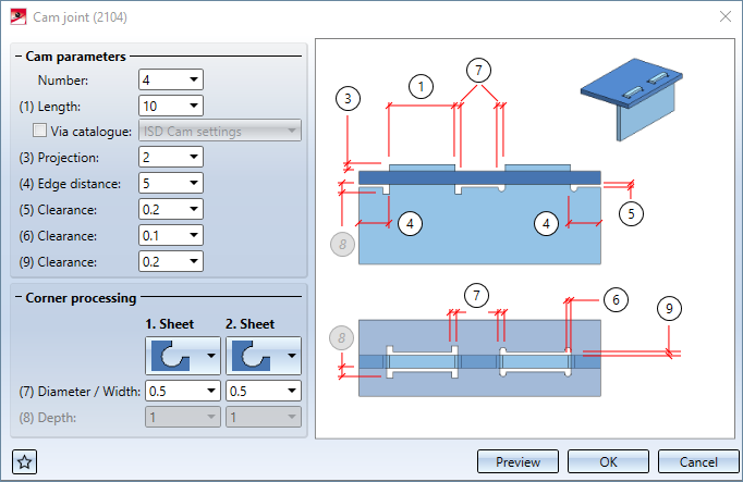
If the connection is possible after selection of the edges, the following dialogue window will be displayed:
|
1st sheet |
|
2nd sheet |
|
|---|---|---|---|
|
|
No corner processing Bore out Cut out radius tangentially Cut out rectangle |
|
No corner processing Bore out Cut out radius tangentially Cut out rectangle Cut out slot shape |
After specifying all required data, you can insert the cam joint. If you select Preview, the cam joint will be applied, but the dialogue window will remain open, enabling you to change parameters and check the result in the drawing if required. If you select OK, the cam joint will be applied, and the dialogue window will be closed. If you select Cancel, the window will be closed, but no changes will be applied.
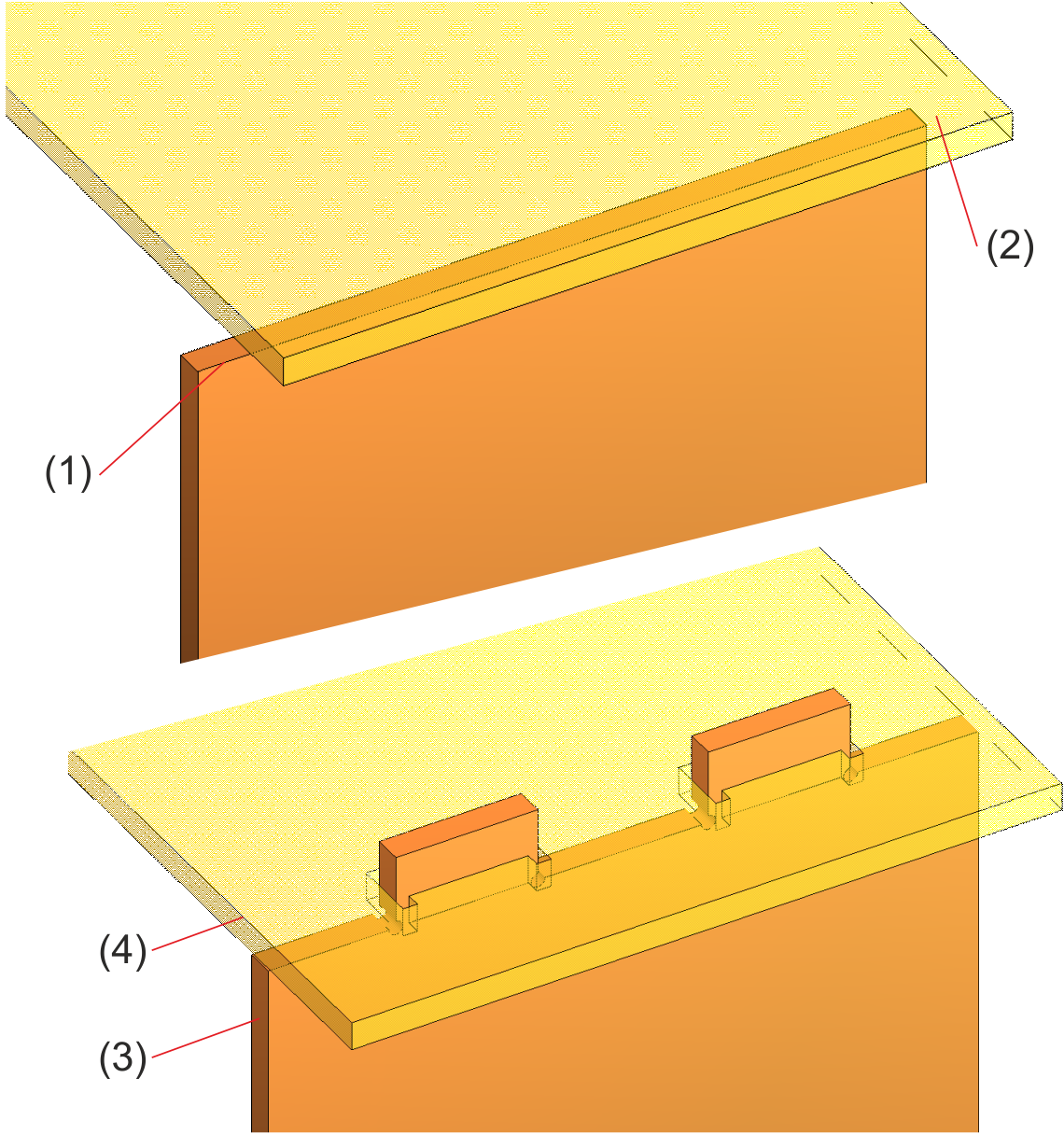
(1) Outer edge of first sheet flange
(2) Select surface
(3) First sheet with 3 mm projection and round corners
(4) Second sheet with rectangular cutouts
 Please note:
At the top of the window you can save a configuration for later re-use, or load already existing ones.


Sheet Metal Design Variants (3-D SM)
|
© Copyright 1994-2020, ISD Software und Systeme GmbH |
Data protection • Terms and Conditions • Cookies • Contact • Legal notes and Disclaimer