Drawing > Itemisation/Detailing > Create detail drawing for selected SE parts 
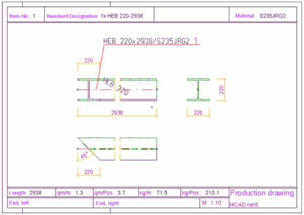
You use this function to create detail drawings for all selected steel engineering parts, i.e. either for the active part or the parts of the active part list (multiple selection).
The prerequisite for creating detail drawings is that the steel engineering parts have been itemised.
Proceed as follows:
- Itemise the steel engineering parts.
- Holding the CTRL key down, identify the Steel engineering parts for which you would like to create a detail drawing. You can do this both in the ICN and in the drawing. You can also select the parts via a rectangle by dragging the desired rectangle with the left mouse button while holding the CTRL key down.
- Select Create detail drawing for selected SE parts
 . The Steel Engineering detail drawing window is displayed.
- Show in view
You can choose here whether you also want sub-parts and boltings to be displayed in the detail drawing as well as main parts. - Additional drawings
If the Detail Steel Engineering sub-parts individually checkbox is active, a separate detail drawing is created for each sub-part. This also applies to steel engineering parts which are sub-parts of a non-steel engineering part. - Layout
To insert a drawing frame, activate the corresponding checkbox and select a frame from the list box of the text field displayed below it. The suggested frames are defined in the StbEtZng_RAHMEN.DAT file in the SYS directory of your HiCAD installation. If desired, you can edit the file by removing unused frames or defining new ones and, in so doing, limit the frames in the list box to those which are actually needed.
Activate the Complete title block checkbox if you want the title block to be filled automatically with the information from the article master and document master. If you do not want to insert a drawing frame (checkmark not set), you can select a scale for the detail drawing from the Scale list box.
- Further handling of drawing
If the Leave detail drawing open checkbox is active, the newly created detail drawing is opened in a new drawing window once the function has ended. To activate this file, click the relevant window icon on the Switch drawing tab in the ICN. If the Save detail drawing automatically checkbox is active, the detail drawing will be saved to the same directory in which the entire drawing is located. The file name is composed of the prefix "CD" and an unambiguous ID which is automatically generated by HiCAD, e.g. CD_263485165. One of the two checkboxes must be active!
- If you choose OK to exit the window, the detail drawings of the highlighted steel engineering parts are created.
![]() Please note:
Please note:
- The drawing frame and the various views of the individual part are listed in the 2-D tab in the ICN. The 3-D tab specifies the part of the detail drawing.
- You can also generate an additional axonometric view automatically in the detail drawing. The settings for this are made in SSWERKST.DAT.
Additional
axonometric view in detail drawing: 7 = axonometric, 8 = upright
axometric, 0 = no
8
Position of axonometric view: -1/1 = left/right of other views, 2 = included,
use free space in view block
-1
You can define the desired axonometry and the position of this view.
- Alternatively, you can use Create+Print to create detail drawings.
- Activating the Save detail drawing automatically checkbox directly when creating the detail drawing enables you to define that the detail drawing is saved locally. However, you can also save it subsequently.
- The SSWERKST.DAT file in the HiCAD SYS directory enables you to specify whether you want to apply the attributes of the original drawing:
Transfer document attributes to individual part drawing 0: no, 1: yes - Konstruktionsattribute in Einzelteilzeichnung uebertragen: 0 = nein, 1 = ja
- If you want to create detail drawings for the entire construction in one step, you can also use the Drawing > Workshop, New function and select the Detail drawings to external drawings option in the Targets area.


