Assigned Text Object
Use the functions in the Text objects group to process the text objects assigned to an isometry or a pipe spool drawing and create user-defined text-objects.
 Please note:
- Semi-automatic part annotation directly in the layout plan is now also possible for particular (including Plant Engineering-specific) attributes, e.g. for standard designation, nominal diameter, article number, KKS number etc. For this purpose, you use the Part annotation, with free text and leader line
 function in the Text function group of the 3-D Dimensioning + Text tab.
 - Please also read the information provided in the Special Attributes in Lists/Text Objects (Iso) chapter.
Edit assigned text object
Isometry + Pipe spool drawing > Text objects > Edit assigned text object 
Plant Engineering > Isometry/Pipe Spool Drawing> Spool  > Edit assigned text object
If no pipeline is active, use the graphic cursor to identify a part in the pipeline you want to process. When HiCAD asks for confirmation, respond with Yes.
Identify the text object with the cursor.
You will get the same dialogue box as for the Create assigned text object function; here, however, you are enabled to process all text objects, i.e. not only the user-defined ones. With this function, you do not create a new text object, but change an existing one.
Select Cancel to end the dialogue box without applying the changes. Select Insert to end the dialogue box and take over the changes.

Create assigned text object
Isometry > Text objects > Create assigned text object 
Plant Engineering > Isometry/Pipe Spool Drawing> Spool > Create assigned text object 
This function enables you to create a user defined text object, i.e. you can specify its composition. HiCAD assigns a specific ID to this type of object. This means that even when a text object contains connection coordinates matching those of an automatically created text object, it is not recognised by automatic functions. For example, if you invoke the Delete connection coordinates function, the user text object is not deleted.
A text object can consist of the following components:
- Part attributes,
- Article master attributes,
- Special characters,
- any alphanumerical texts,
- Pipe properties,
- Pipe class properties, and
- User-defined Plant Engineering attributes.
Proceed as follows:
- Specify the point where the text tag is to be placed. The following options are available:
Selection acc. to part (Default setting after function call)
Here the text object can be placed at an arbitrary point beside the selected part. Move the cursor over the part. The location where the text object is to be created will be marked with a coloured sphere (Special colour Marking 3).
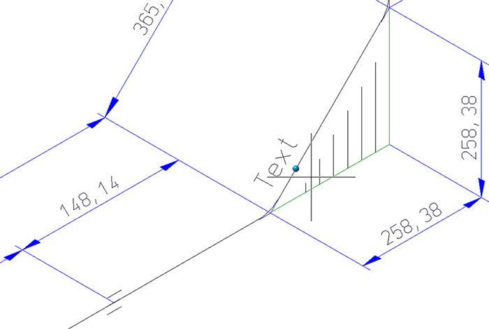
Click to apply a marked point. The Item number dialogue window (see 2.) will then be displayed.
Selection acc. to points
As long as you are asked to place the text tag (i.e. as long as the Item number dialogue window has not been opened), you can right-click to open the following context menu:
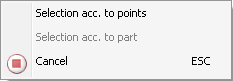
There you can find the Selection acc. to points function. This function allows you to specify the position of the text object with the help of the HiCAD point options. A possible example would be the placing of the text object next to the centre of a pipeline.For this to happen, you need to move the cursor near the desired pipe; the HiCAD Autopilot will then automatically suggest point option M. Confirm with a mouse click. After calling the function, the part that is nearest to the current cursor position will be highlighted (Special colour Marking 1).
You can now specify any point using the Autopilot or the Point options. This point needs not necessarily be located on the part. After specifying the point, the Item number dialogue window will be displayed. If you want to go back to the Selection acc. to part mode before specifying the point, right-click and choose the function in the context menu.
Select Cancel or ESC to cancel the function.
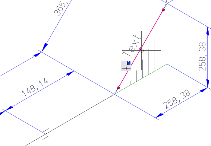
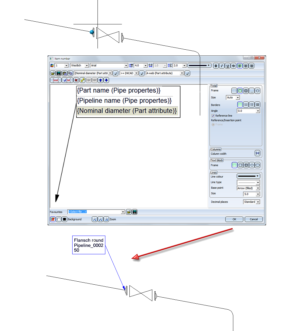
- The Item number dialogue window will be displayed. The window is largely operated in the same way as the Item number dialogue window for 3-D annotations.
- Select the components of the text object and specify the required settings for the representation.
- Confirm with OK.
- If you have activated the Reference line checkbox in the Total area of the dialogue window, also specify the start point, the end point and the inflexion points of the line.
Please note that the settings on the Text/Lines tab of the Isometry: Settings dialogue window will be considered during placing of the text object.
Extensive information on annotations and other examples can be found in the Change Annotation Settings (3-D) Help topic.
Annotating connecting points of a pipeline:
When annotating coordinate points on pipelines you can also add information on inserted components:
The example shows a very simple formatting, without frame or similar elements; the formatting can be specified further by the user. The local connection number is part of a consecutive numbering of all open end points of the pipeline and is not to be confused with the connection number.
In the case of connected pipelines in other isometries, this consecutive number is used as a "remote connection number". For vessels, the number of the respective connecting point is used.
Move assigned text object
Isometry + Pipe spool drawing > Text objects > Move assigned text object 
Plant Engineering > Isometry/Pipe Spool Drawing> Spool > Move assigned text object 
If no pipeline is active, use the graphic cursor to identify a part in the pipeline you want to process. When HiCAD asks for confirmation, click Yes.
Identify the text object with the cursor. You can specify an angle point with the right mouse button, the endpoint with the left mouse button and the position of the text object. The leader line only appears if the appropriate option has been preset.
Delete assigned text object
Delete assigned text object 
If no pipeline is active, use the graphic cursor to identify a part in the pipeline you want to process. When HiCAD asks for confirmation, respond with Yes.
When you identify the required text object with the cursor HiCAD immediately deletes it.
This function is only available in the context menu of the isometry (right-click on a part in the isometric drawing)!
Assign view
Assign view 
Use this function to distribute the annotation in pipe spool drawings over several views by assigning text objects to a different view.
Proceed as follows:
- Right-click the desired text object. The Pipe spool drawing - Text objects will be displayed.
- Activate the Assign view function.
- Select the view to which you want to assign the text object by clicking the view frame in your drawing.
This function is only available for pipe spool drawings!
Example:
In the left view the Assign view function has been applied to the text objects (1) and (3), and then the view (2) has been selected.
After execution of the function:

Isometry and Pipe Spool Drawing (PE/Iso) • Isometry and Pipe Spool Drawing Functions for the Layout Plan (PE) • Plant Engineering Functions