Settings - Automatic Dimensioning

Plant Engineering > Isometry / Pipe Spool Drawing > Pipe spool drawing settings 
Isometry + Pipe spool drawing > Settings 
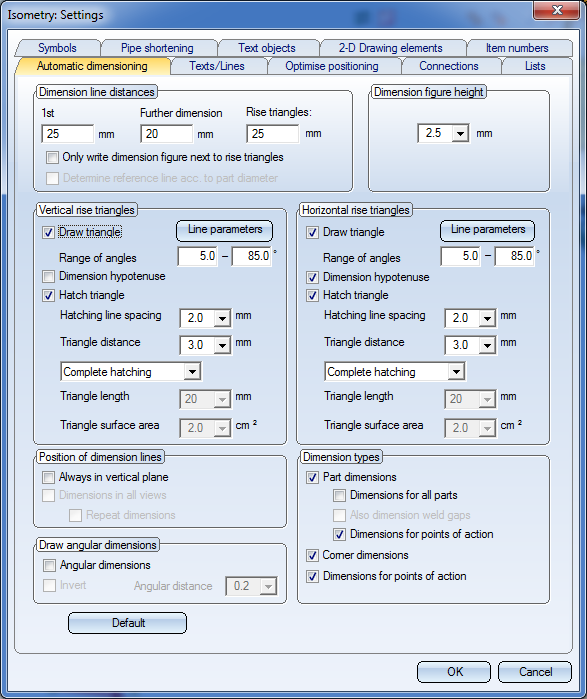
Use the setting options on the Automatic dimensioning tab to specify the pre-settings for the automatic dimensioning.
If you want to dimension the arcs of bent pipes to facilitate processing on bending machines, activate/deactivate the desired checkboxes in the Draw angular dimensions area at the bottom left.
The dialogue window consists of the following areas:
- Dimension line distances / Dimension figure height
- Vertical / Horizontal rise triangles
- Position of dimension lines
- Dimension types
- Draw angular dimensions

Dimension line distances / Dimension figure height
- 1st dimension line
Here you specify the distance of the first dimension line to the reference line. The reference line is the centre line of the part or, if the Determine reference line according to part diameter checkbox is active, a virtual line in the dimensioning plane which runs parallel to the centre line with a distance of D / 2, with D being the outer diameter of the part. - Further dimension lines
Here you specify the distance of the dimension line to each other. The distance will be used if there are several dimension lines.
- Determine reference line according to part diameter
If this checkbox is active, not the centre line will be used as the reference line for the determination of the position of the first dimension line, but a virtual line in the dimensioning plane which runs parallel to the centre line with a distance of D / 2, with D being the outer diameter of the part. This checkbox is only available for pipe spool drawings.

(1) Dimension line distance of 1st dimension line, Determine reference line... checkbox is active; (2) Dimension line distance of further dimension lines, (3) Dimension line distance of 1st dimension line, Determine reference line... checkbox is not active
- Dimension figure height
Enter the desired height of the dimension figure into the input field.
- Only write dimension figure next to rise triangles
Normally, each of the three edges of a rise triangle obtains a linear dimension. The dimension figure of such a linear dimension indicates the length (in mm) in the corresponding spatial direction. The dimensioning of all rise triangle edges by means of linear dimensions as well as the many other dimensions can sometimes make the representation of pipeline isometries confusing.
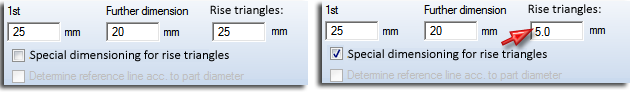
To avoid this, HiCAD offers the option to place only dimension figures (instead of complete linear dimensions) next to the edges of rise triangles. To do this, activate the Only write dimension figure next to rise triangles checkbox.
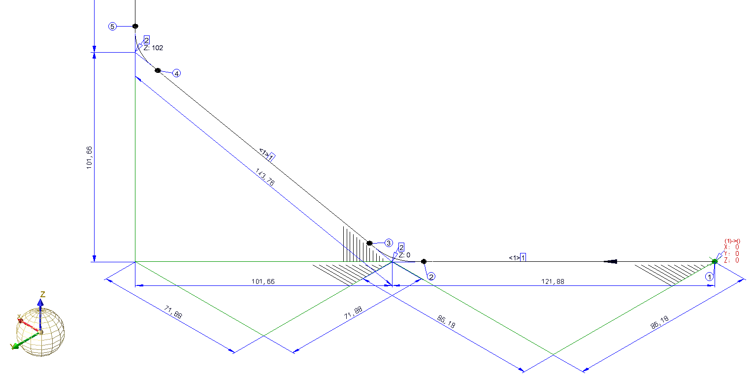
Linear dimensions on rise triangles - No special dimensioning for rise triangles
When the linear dimensions are removed, the dimensioning of the rise triangles is much clearer, and the overall view is less confusing. The dimension figure is placed centrally next to the relevant edge. The distance to this edge can be entered as a separate dimension distance into the Rise triangles input field. If the distance is positive, the dimension figure will be placed outside of the rise triangle, if the distance is negative, the dimension figure will be placed inside of the rise triangle. If the value is 0, the dimension figures will be placed onto the relevant edge.
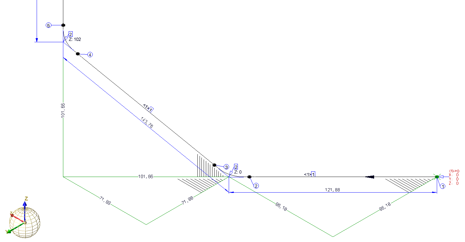
Rise triangles only with dimension figures
If the Only write dimension figure next to rise triangles checkbox is deactivated, linear dimensions will be used for the rise triangles, but with the dimension distance entered in the Rise triangles checkbox. If the checkbox is deactivated, and the same dimension distance is set for Rise triangles and 1st dimension line, the behaviour will be the same as in older HiCAD versions (before HiCAD 2100.0).
Vertical / Horizontal rise triangles
Amongst other things, pipeline isometries in the Plant Engineering module serve the purpose of visualizing complex, three-dimensional pipeline constructions in such a way in 2-D, that this visualisation still gives a good impression of the spatial pipeline routes. If a straight pipeline does not run parallel to a coordinate axis, rise triangles can be inserted to convey a better impression of the spatial position of such a pipeline. Here, you distinguish between vertical and horizontal rise triangles:
- Vertical rise triangles are rise triangles the surface normal vector of which runs perpendicular to the Z-axis of the drawing coordinate system.
- Horizontal rise triangles are rise triangles the surface normal vector of which runs in the direction of the Z-axis of the drawing coordinate system. Horizontal rise triangles can only be activated if the vertical ones are also activated.
For rise triangles you can specify, separately for vertical and horizontal rise triangles:
- whether rise triangles are to be drawn and, if so, for which range of angles,
- whether the hypotenuse of the rise triangle is to be dimensioned,
- the distance of the hatching lines,
- the distance of the triangle to the pipeline,
- whether the triangle surface is to be hatched, and if so, how.
Concerning the hatching you can choose between the following two options:
- Complete hatching
The rise triangles are drawn with complete hatching. As a possible result, the rise triangle may be optically too prominent in the drawing. Also, complete hatchings can often overlap with other drawing elements: For example, the vertical rise triangle in the image below overlaps with the length dimensioning of the triangle cathetus. - Partial hatchings
Only a part of the rise triangle obtains a hatching. For example, the horizontal rise triangle in the image below has a partial hatching. The hatching itself has a triangular form, which is mathematically similar to the outer, unhatched green rise triangle further down the page. The size of the hatched triangle can either be determined by specifying the Triangle length or the Triangle surface area.
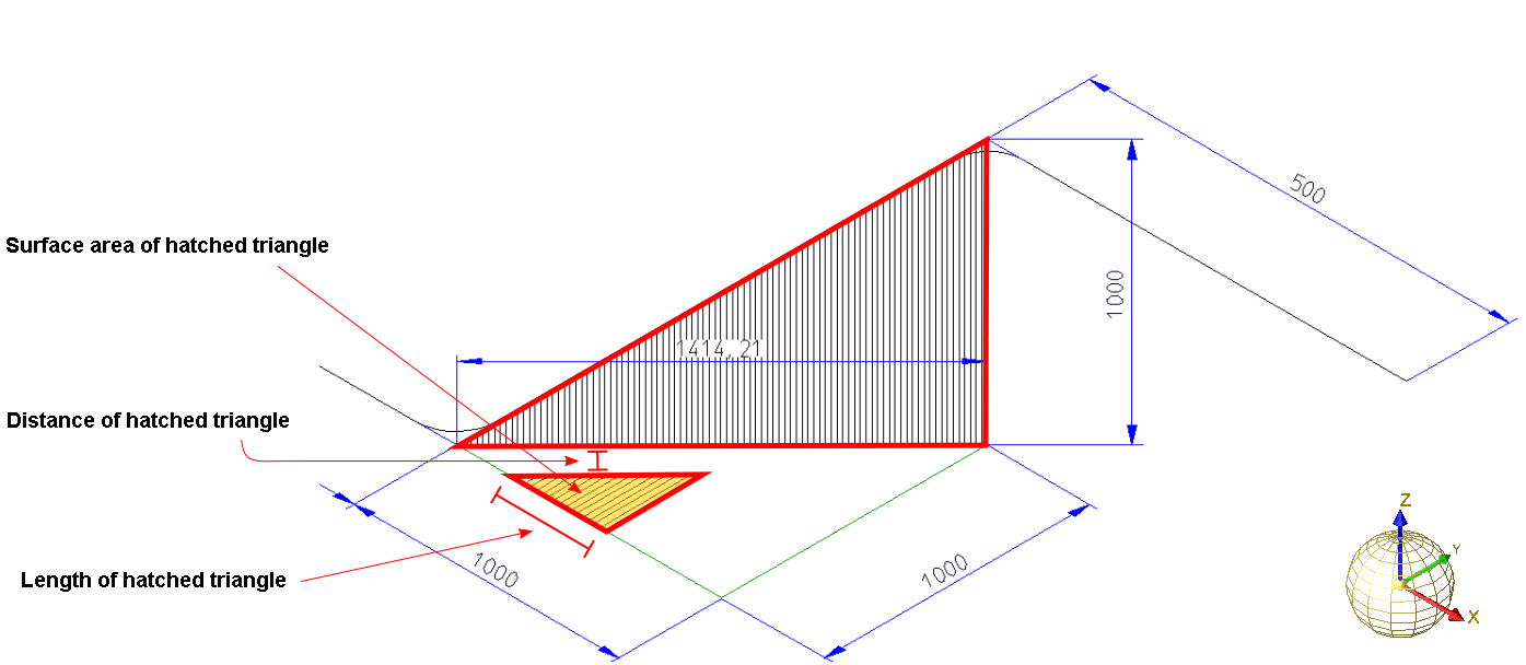
Vertical and horizontal rise triangle
If you select the Triangle surface area option for the hatching, the length of the corresponding hatching will be calculated by HiCAD accordingly. The effect of this setting is that an acute angle between hypotenuse and start cathetus leads to a longer hatching distance that an obtuse angle. Visually, the hatching in both rise triangles are equally intense. The result is a significantly enhanced impression of the three-dimensional route of the pipeline.
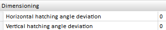
The vertical and horizontal hatching angles are automatically calculated to provide a best possible visual representation. However, if you prefer angles deviating from the automatically calculated angles, you can specify the desired difference angle in the Configuration Editor, at Plant Engineering > Isometry and Pipe spool drawing:
Offset triangles in front of pipelines if possible
If a straight pipe is not located in one of the three basic coordinates, you can, for the sake of a better spatial representation, insert two rise triangles:
- a horizontal rise triangle in the XY-plane to convey an impression of the horizontal route, and
- a vertical rise triangle within the plane created by the Z-axis and the projection of the straight pipeline onto the XY-plane to convey the vertical route.
If the two rise triangles overlap, the horizontal rise triangle will be mirrored (flipped) at its hypotenuse, thus avoiding an intersection. If a pipeline isometry has several areas with two rise triangles, the number of all overlaps of rise triangles will be determined in a first step. If more that half of the rise triangles overlap, all horizontal rise triangles in the complete pipeline will be flipped. The advantage of this procedure is that the cathetus between start point and base point of all horizontal rise triangles either runs in the direction of the positive Y-axis or in the direction of the negative Y-axis. Thanks to this consistent orientation, the observer does not need to re-orientate him/herself for each rise triangle and gets a better spatial impression of the situation.
 Interactions between rise triangles and down-grade symbols:
Generally, down-grade symbols suppress vertical rise triangles. This means that no vertical rise triangle will be placed next to a pipeline section that already has a down-grade symbol. If the route of the section has an offset to the coordinate axes, a horizontal triangle will still be created (provided that the corresponding setting has been set).
 These options are only available for isometries and not for pipe spool drawings!
Position of dimension lines
- Always in vertical plane
If this checkbox is active, the dimension lines and the part centre lines to which the dimension refers are always located in one plane that is perpendicular to the XY-plane of the World CS.
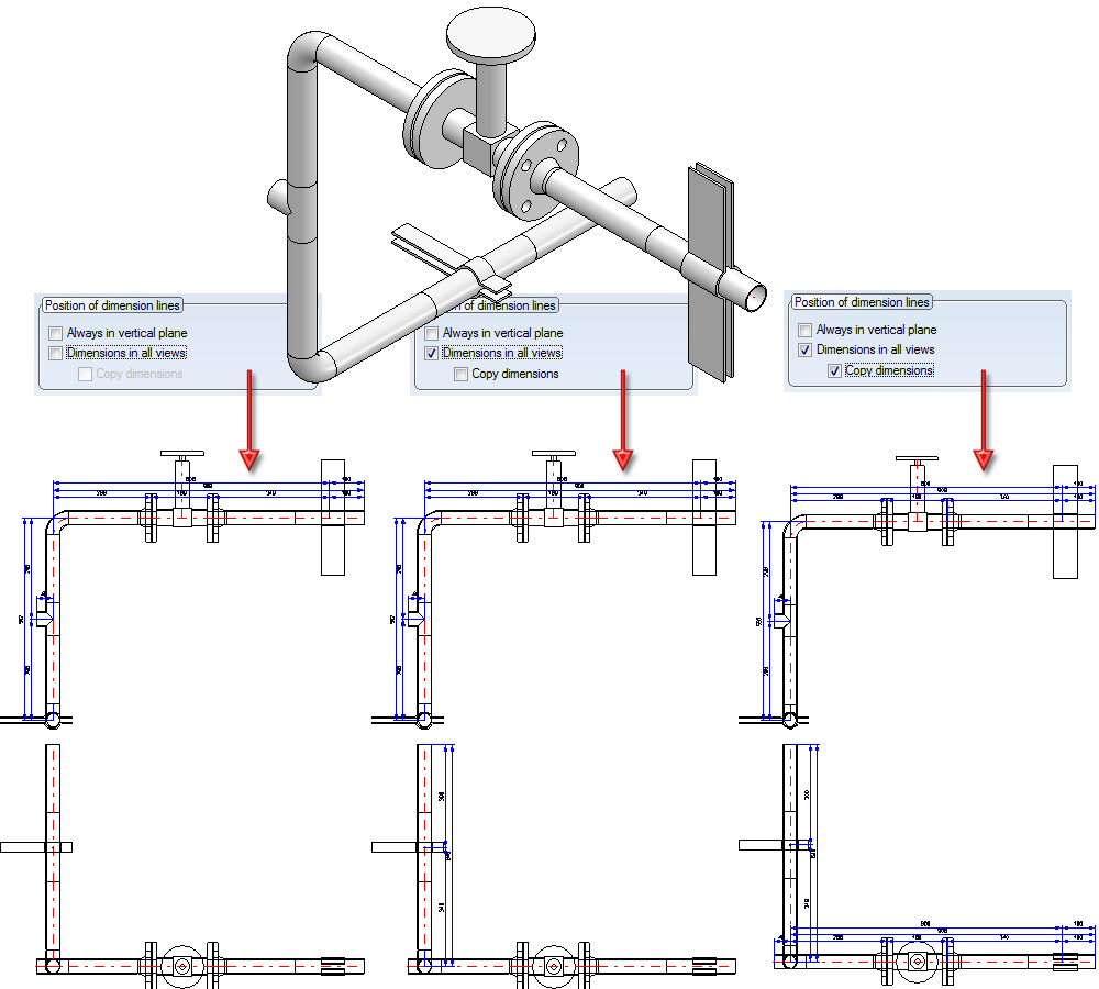
- Dimensions in all views / Repeat dimensions (only for pipe spool drawings)
Activate the Dimensions in all views checkbox to create dimensions in all views of a pipe spool drawing. The procedure is as follows:
- If both checkboxes are active, all reasonably displayable dimensions will be created in all view, even if they will then occur in more that one view.
- If the Dimensions in all views checkbox is activated, and the Repeat dimensions checkbox is deactivated, each dimension will be shown not more that once (if there is a view at all where the dimension can be displayed).
- If the Dimensions in all views checkbox is deactivated, only the view with the highest priority will be dimensioned.
- Default
Click this button to enter the default settings in the dialogue box. These default settings are specified in the system file ANL3DBEM.DAT (in the \hicad\sys file). You can edit the file with a suitable Editor (e.g. the Notepad). In addition, you can determine there whether the default parameters are to be used upon each new start of HiCAD. If not, the settings that were last specified in the dialogue box will be used.
- Line parameters
Click this button to call a selection dialogue for the line parameters ( colour, line type, layer). The settings will only apply to the assigned rise triangles. Colour and layer settings also apply to the hatching of the triangles.
Click OK to apply the settings shown in the dialogue box. Click Cancel to discard the selected settings.
Dimension types
Specify which dimensions are to be generated by activating or deactivating the corresponding checkboxes.
- Part dimensions
Parts and components of the pipelines will be dimensioned. One distinguishes between Dimensions for all parts and Dimensions for points of action. If the Dimensions for all parts checkbox is activated, the Also dimension weld gaps option is also available. Activate this option if you also want to dimension the weld gaps.
- Corner dimensions
Dimensions the pipeline via its corner points.
- Dimensions for points of action
Dimensions the pipeline via its points of action.
In (2) and (3), only parts with flange connections are individually dimensioned.
Draw angular dimensions
Besides the common functions for the dimensioning of angles on the 3-D Dimensioning + Text tab, you have the option to automatically generate the angular dimensions between the straight pipe segments of a bent pipe. For this to happen, activate the Angular dimensions checkbox.
The following image shows the dimensioning of two automatically generated angles:
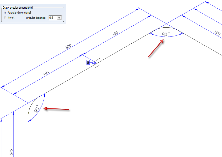
Use the settings beneath Draw angular dimensions to determine the distance and the orientation of the drawn angles.
Angular distance
This value determines the distance of the drawn angles to the intersection point of their legs.
Invert
You determine the orientation of the angular dimensions by activating or deactivating this checkbox, i.e. you determine whether the angle dimensions are to be drawn between their respective legs, or the opposite counter-angles are to be dimensioned. If the checkbox is active, the opposite counter-angles will be dimensioned.
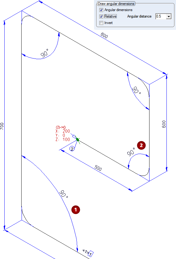
Relative
If this checkbox is active, the two pipe lengths of the adjacent legs are to be considered for the calculation of the distance of the angular dimension. The longer the two pipe segments of the adjacent two legs, the greater will be the extension of the angular dimension. This means: The longer the pipes, the more space will be occupied by the angular dimension in the isometry.
In the following image the dimensioning has been created with the setting Invert. Here, all angles have an equal extension, irrespective of the length of the adjacent pipe segments.
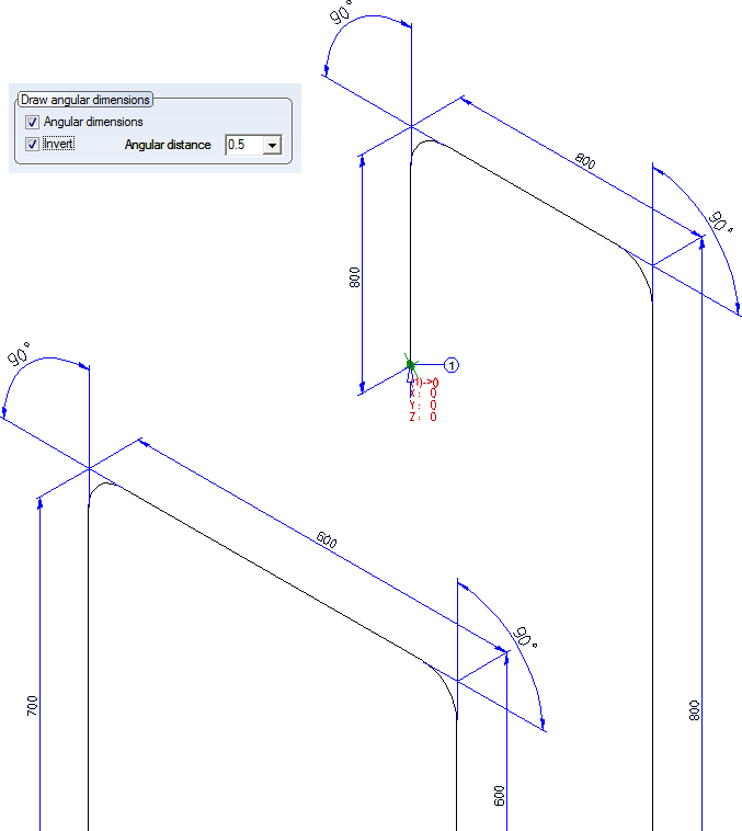
In the next image, the settings Relative: YES and Invert: NO have been selected. Here, the angular dimensions for the longer pipe segments, e.g. (1) are larger than thoise for the shorter pipe segments, e.g. (2).
Please note:
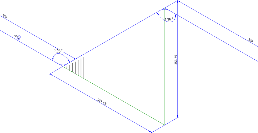
If the angles to be dimensioned are not perpendicular, and the Rise triangles function has been activated, the dimensionings will still remain clearly visible, since the rise triangles are by default only implied by means of a hatching that does not overlap the angular dimensions. As a result you will obtain a clear representation of the bent pipeline in space, while the added angular dimensions will remain easily readable.

Settings (PE/Iso) • Isometry and Pipe Spool Drawing (PE/Iso) • Isometry/Pipe Spool Drawing Functions for the Layout Plan