Settings - 2-D Drawing Elements
Plant Engineering > Isometry / Pipe Spool Drawing > Isometry settings 
Plant Engineering > Isometry / Pipe Spool Drawing > Pipe spool drawing settings 
Isometry+Pipe Spool Drawing > Settings 
 The following description refers to isometries and pipe spool drawings.
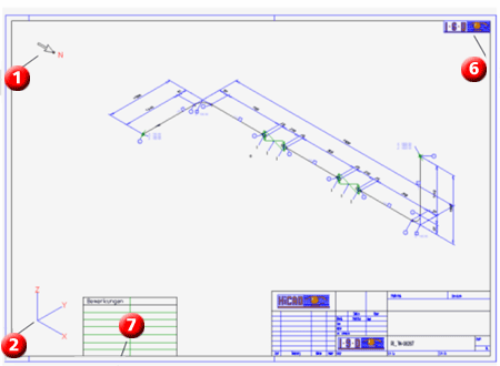
The positioning of certain 2-D isometry drawing elements in a drawing frame can be preset in the 2-D Drawing elements tab. Furthermore, you can pre-set the position of some elements in the drawing frame, such as the north arrow or lists. In addition, it is possible to include and position arbitrary 2-D drawing supplements existing as FGA files.
|
Contents |
|
|
(1) |
North arrow |
|
(2) |
Tripod |
|
(3) |
Bill of materials |
|
(4) |
Length list |
|
(5) |
Connection list |
|
(6) |
LOGOISD.FGA |
|
(7) |
TEXTTAB1.FGA |
The elements north arrow, tripod and the three list types cannot be removed from this table. If they actually appear in the isometry depends on whether they are activated in the isometry dialogue.
FIG files can be entered and removed. If a file has been entered, the associated graphic appears in the isometry after its generation.
- Insert file
Right-click the table to open a context menu. Choose Insert and, after clicking the button that appears in the Content column for the newly created row, select the required file. - Remove file
Right-click the entry you want to remove. When the context menu appears, select Remove. The row is deleted.
Meaning of the columns
- 1st column: Contents
Isometry element or name of FGA file - 2nd column
If the 1st column contains a file name and the file is located in a HiCAD directory specified in FILEGRUP.DAT, the associated ID is shown in this column. - 3rd column: Path
If the 1st column contains a file name and the file is not located in a HiCAD directory specified in FILEGRUP.DAT, you will find the directory path in this column. If it is a sub-directory of a HICAD directory, the subdirectory name is shown in this column, and the ID for the HiCAD directory in the 2nd column. - 4th column: Orientation
This column provides several orientation options for elements. If you select Position from the pull-down menu you are enabled to further specify the position via entries in the 5th and 6th column.
The „right“ or „left“ positioning options place elements near the right/left frame border, one after the other, from top to bottom. The positioning options "top" and "bottom" place the elements near the top/bottom frames, one after the other, from left to right. User -defined elements (company logos etc.) are always inserted last.
Please also read the notes on BOM alignment in the topic Settings - Lists.
- 5th/6th column: X-Pos/Y-Pos
If you selected the Position option in the 4th column (Orientation), you are enabled to specify the position via values between 0 and 100. Reference point is the bottom left-hand corner of the drawing frame, i.e. 0 means "bottom/left", 100 means "top/right".
The settings shown above are reflected in the sheet configuration as follows(the lists 3-5 have not been activated in the isometry dialogue):

Default
Use the Default button to create a simple "empty" pre-setting, containing only the elements North arrow, Tripod and the three list types.

Settings (PE/Iso) • Isometry and Pipe Spool Drawing (PE/Iso) • Isometry/Pipe Spool Drawing Functions for the Layout Plan (PE)
