Process Guidelines
Plant Engineering > Guideline Tools > Process guidelines 
Activate the function and identify the c-edge you want to process. As for the creation of guidelines, the Process c-edge dialogue window appears. The edges and points of the c-edge will be displayed in the pre-set colours.
You have the following options:
- Mark c-edge points
- Insert/Remove C-edge points
- Move c-edge points
- Add X/Y/Z-value
- Divide edges
- Divide edges n times
- Process axes
- Hide/Show axes
Use the Undo  option to undo previous processing steps, and the Redo
  option to restore undone processing steps.
You can end the processing via the dialogue box or via the context menu (RMB) at the graphic cursor.
Select Cancel to reject the guideline and delete it from the graphic. The window is closed and the function is ended. Select OK/Apply to accept the guideline and insert it in the layout plan.The window is closed and the function is ended.

Mark C-edge points
Some processing functions refer to one or several marked points. Generally, c-edge points can be marked in two ways:
- Via graphic cursor
Move the cursor on the point you want to mark and click the left mouse button. To mark further points, press and hold down the CTRL key and left-click at the required cursor position.
You can also mark an entire sequence of points at once: Mark the first point, press and hold down the CTRL key and select the last point of the point sequence you want to mark.
If you click on any c-edge point again, all markings are removed.
The marked points are displayed in the pre-set colour. At the same time, the corresponding rows in the coordinates table are highlighted.
- Via coordinates table
Select the row for the c-edge point you want to mark. Use the CTRL and SHIFT keys to select several rows and mark the corresponding points.
At the same time, the c-edge points in the graphic are displayed in the pre-set colour.
Insert/Remove C-edge points
Insert
To insert a new c-edge point, right-click an empty row in the coordinates table and select the Insert function from the context menu.
A new row is inserted, initially suggesting the values of the previous row. You can now change the coordinates and specify the position of the new point.
If you want to insert further points, right-click the empty row under the last row.
Remove
Mark the points you want to delete, right-click to open the context menu in the coordinates table or at the graphic cursor and select Remove.
Move c-edge points
Mark the points you want to move:
- Via the graphic cursor
Press and hold down the CTRL key and move the graphic cursor on the point you want to mark. Now press and hold down the left mouse button and drag the points to the required new position. Or right-click to call the context menu and select Move. - Via the coordinates table
In the coordinates table, open the context menu with a right-click and select Move. Move the points in the graphic to the new required position using the mouse.
The graphic cursor is dropped at the coordinates indicated in the row you had previously right-clicked.
Add X/Y/Z-value
Use this function to add a positive or negative value to a coordinate of the marked points, causing a moving of the points in the direction of the selected coordinate axis.
Mark the points you want to modify. Right-click the column for the coordinate to be changed and select Add X-value (respectively. Add Y-value or Add Z-value). An input field is displayed in which you can enter the value for the coordinate change. Select OK to execute the change. It will become visible as soon as you move the mouse pointer into the graphic window.
Divide edges
An edge defined via two points is divided by automatic insertion of a new point in the mid point of the edge.
Mark the end points of the edge you want to divide. Right-click one of the marked rows in the coordinates table to open the context menu and select Divide.
Divide edges n times
An edge defined via two points is divided into n+1 edge segments of equal length by automatic insertion of n new points.
- Mark the end points of the edge you want to divide.
- Right-click one of the marked rows in the coordinates table to open the context menu.
- Select the menu item Divide, n times.
- An input field is displayed in which you can enter the number of the new points.
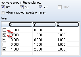
Insert/Remove axes
As default, three axis directions are pre-set and activated, running parallel to the active coordinate system. If for an axis a value is specified in only one column, this means that this axis runs parallel to the corresponding coordinate axis of the active coordinate system World CS or Local CS). The amount of the value is irrelevant in such cases.
An axis may also deviate from the direction of the coordinate axes. For instance, if the values for X and Y are 1 and the Z-value is 0, there will be an axis direction running parallel to a straight line lying in the XY-plane of the active coordinate system and forming a 45° angle with the X-axis.
You can insert further axes in the table, activate, deactivate or delete them, depending on your requirements.
- Insert axis
Right-click the axes table to open the context menu and select Insert. A new row is inserted for the new axis whose values are different from those for the already existing axes. You can now change the suggested values as required. Double-click the value you want to change and confirm with ENTER. - Remove axis
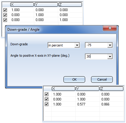
Right-click the row for the axis you want to delete and select Delete in the context menu. - Down-grade / Angle
If you right-click the row of the axis and select the Down-grade / Angle function in the context menu, you can specify the direction of an axis further. Change the values for Down-grade (percent, degrees, mm) and/or Angle and confirm with OK. The selected axis is recalculated accordingly.
Use the Reset to default function in the context menu of the axis table (right-click an empty row of the axis table) to reset the axes alignment, i.e. the axes are then parallel to the coordinate systems again.
Hide/Show axes
Axes can be activated/deactivated directly in the Process c-edge dialogue window.
If you have defined a greater number of axes for the routing of guidelines, the identification of a particular axis may be difficult owing to the multitude of axes. In such cases, the deactivation of axes in the axes table is also rather difficult.
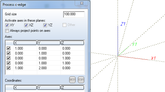
In such cases you have the option to switch axes on or off that are located in the planes spanned by the axes of the active coordinate systems. If you want to hide axes in a particular plane, deactivate the corresponding checkbox below Plane. Activate the Others checkbox to hide/show axes which are not located in one of these planes.
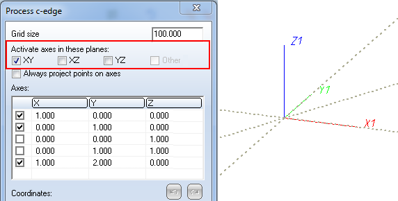
In this example, only the axes located in the XY-plane are switched on.
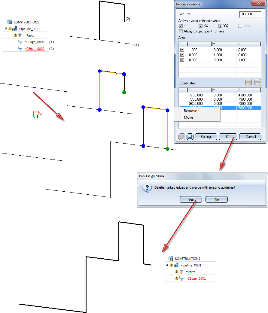
Delete/trim edges
As with the insertion of a new guideline,HiCAD checks during the processing of already existing guidelines whether the relevant pipeline contains a guideline on which the start point and also the end point of the processed guideline is located.
If this is the case, the edges that would be trimmed away will be highlighted. At the same time, an appropriate message will be displayed.
If you confirm the trimming, the two guidelines will be merged into one.
An example:
The image below shows 2 guidelines of a pipeline. The start point of Guideline 2 lies on Guideline 1, but the end point does not. When inserting this guideline, no Trim option will therefore be offered. But if you not modify Guideline 2, moving, for example, its end point onto Guideline 1, you can trim. If you confirm the message with Yes, the highlighted edges will be removed and the two guidelines will be merged into one: