Local Coordinate System

Plant Engineering > Settings > Others > Local coordinate system

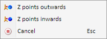
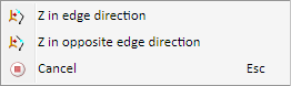
Use the functions of this menu to influence the local coordinate system.

Set on connection
Use this function to snap the required connecting point with the Autopilot. A preview of the coordinate system will then be displayed.

As long as no point has been selected, the following context menu can be activated with a right-click:

The functions of the menu allow you to choose whether the Z axis of the coordinate system is to be oriented in the direction of the connection surface vector or in the opposite direction. The local coordinate system is now placed so that its origin is at the selected connection point and the Z-axis points in the selected direction. The Y-axis is aligned in such a way that it lies in a plane parallel to the XY-plane of the World CS.

Set on guideline
When you identify an edge, the local coordinate system will be set on the edge. If you move the cursor over the corresponding guideline, a preview of the coordinate system will be displayed.

As long as no edge has been selected, the following context menu can be activated with a right-click:

Here you can select whether the origin should be at the start or end of the edge. The Z-axis is always aligned in (or in opposite) edge direction. The Y-axis is aligned in such a way that it lies in a plane parallel to the XY-plane of the World CS.

New origin
This option enables you to move the coordinate system by selecting a point option and specifying a new CS origin.

Activate World CS
This function switches to the World CS.

Plant Engineering FunctionsPlant Engineering Settings