Variant for Part Type: Flange
Rules for the creation of Feature Variants for Plant Engineering parts
|
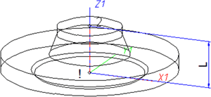
Position of connecting points and determination of insertion lengths for various connection types |
|||
|---|---|---|---|
|
Connection for butt welding |
Flange connection |
Connecting nipple for |
Connecting socket for |
|
|
|
|
|
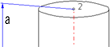
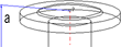
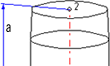
| a = Insertion length dimension (e.g. L, L1 etc.) |
a = Insertion length dimension (e.g. L, L1 etc.) |
a = Insertion length dimension (e.g. L, L1 etc.) |
a = Insertion length dimension (e.g. L, L1 etc.) |
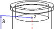
Named isolated points
|
Designation |
Purpose |
Comment |
Position in coordinate system |
|---|---|---|---|
|
! |
Connecting point |
Fitting point |
in origin (0,0,0) |
|
2 |
Connecting point |
|
X = 0, Y = 0, Z > 0 |
|
Name |
Designation |
Attribute (optional) |
|---|---|---|
|
L |
Distance between point “!“ and “2“ |
LAENGE |
If the variables names given in the Name column are used, you do not need to assign any attributes to them via the Variant Editor. If different variables are required, you need to assign the attributes given in the Attribute column...
VAA file
Use the Variant Editor to enter the suitable part type into the VAA file.
Then, use the Variant Editor to expand the VAA file in such a way that it contains values for the sizes specified here, and that the predefined attribute assignment is entered:
|
Parameter All dimensions must be specified in millimetres; |
Variable |
Assigned attribute |
|---|---|---|
|
Nominal diameter, Connection “!“ and “2“ |
N |
NENNWEITE |
|
|
||
|
Additionally (only if the corresponding standard uses nominal diameters in inches): |
||
|
Nominal diameter (inches), Connection “!“ and “2“ |
NI |
N_INCH |
|
Nominal diameters in inches need to be entered as decimal values as well (e.g. 1.5 for 1 1/2‘‘). |
||
|
|
||
|
For connecting sockets these parameters refer to the pipe to be inserted: |
||
|
Outer diameter , Connection “2“ |
D |
D_AUSSEN |
|
Wall thickness, Connection “2“ |
S |
WANDDICKE |
If required, the attribute LAENGE needs to be assigned to the length variables (see Variables names above).
For flangings, an additional variable F1 is available, which determines the distance of the loose flange from connecting point 1 of the flanging. For flangings (welding necks, collar pieces etc) , F1 normally equals the wall thickness.
For variant synchronization you also need to enter the values for the attributes which are to apply to all sub-types of the variant.
Values must be entered for at least the following attributes:
|
Attribute |
Description |
|||||||||||||||||||||||
|---|---|---|---|---|---|---|---|---|---|---|---|---|---|---|---|---|---|---|---|---|---|---|---|---|
|
BENENNUNG |
Designation of the part |
|||||||||||||||||||||||
|
COMPONENT_TYPE |
Part type (always = Semi-finished material + Plant Engineering) for HELiOS database only |
|||||||||||||||||||||||
|
NORMBEZEICHNUNG |
Standard designation of the part (identical for all sub-types!) An entry is mandatory, even if the part corresponds to no standard. |
|||||||||||||||||||||||
|
|
|
|||||||||||||||||||||||
|
ANSCHLUSSART |
Connection type for connection “!“ (always flange connection) |
|||||||||||||||||||||||
|
ANSCHLUSSART2 |
Connection type for connection “2“ |
|||||||||||||||||||||||
|
Possible values of the attribute ANSCHLUSSART (CONNECTION_TYPE):.
The last character (x) provides information about the meaning of the supplement: 0 =No supplement 2 = The supplement consists of connection number, part type, ID, and standard of the part to be connected The prefixed connection number indicates the connection with which the auxiliary part is to be attached to the current connection.
|
||||||||||||||||||||||||
 Loose flanges are assigned to the part type Flange. The attribute ANSCHLUSSART (=CONNECTION_TYPE), however, must have the value 20100!
 Handling of nominal diameters in inches in the HELiOS database:
During part data synchronization, nominal diameters in inches will be taken over to the attributes N_INCH, N2_INCH and N3_. The usual character strings for indication of the diameter in inches (e.g. 1 1/2‘‘ instead of 1.5) will be auto-generated in the database for the attributes NPS_INCH, NPS2_INCH und NPS3_INCH.

Model welding necks as flanges
As an alternative to the modelling of flangings as straight pipes, flangings can also be modelled as flanges if desired.
When using this procedure, the flanging must be of the type "Flange", while the loose flange is an asymmetrical fastener. The flange connection of the flanging must have the connection type 20600. The 6 coming in the third place encodes the asymmetrical fastener with flange connection, i.e. normally a loose flange classified as fastener. For this procedure the variable F1 will also determine the distance of the loose flange to connecting point 1 of the flanging. For welding necks, F1 normally equals the wall thickness.
In contrast to flangings that are modelled as straight pipes, the flange symbol is assigned to the flanging here. This ensures that the position of the flange symbol in a generated isometry will not be affected by a possible moving of the loose flange.
Please note:
If you want to fix the loose flange by a welding point, you should not model it as a fastener, as fasteners do not support welding points on connecting points 2. In this case you must use genuine loose flanges, i.e. such flanges that are actually classified as flanges.
