Fit Nozzle in Vessel - Step 4
Plant Engineering > Part Tools > Fit nozzle in vessel > Specify type of insertion and fit nozzle
The dialogue box Fit nozzle in vessel is displayed.
Type of insertion
Use the first three buttons to fit a straight pipe, and the fourth button to fit an elbow.
|
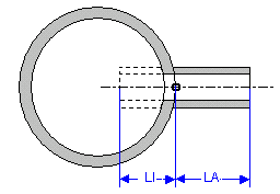
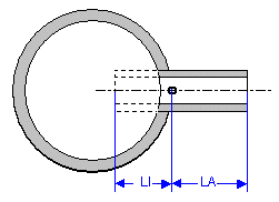
Mounted pipe This function can be used with hollow or solid bodies. The pipe is mounted on the vessel wall and cut to the outer surface. The vessel wall is bored to match the internal diameter of the pipe. For Length, external (LA), specify the required pipe length from the isolation point to the centre point of the front surface on the inner nozzle end to be cut. Please select a length for LI that ensures that the pipe is long enough to allow for the curve of the vessel wall. The required length L is returned by L = LI + LA . The following illustration shows a top view of the relationship of a cylindrical vessel and a nozzle fitted vertical to the bounding surface:
|
|
|
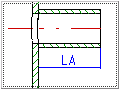
Inserted pipe, projecting This function can only be used for hollow bodies. The pipe is inserted through the wall of the vessel and the cut straight. For Length, Outer (LA), enter the required pipe length from the isolated point to the centre point of the connection surface of the outer end of the nozzle. For Length, inner (LI), enter the distance from the isolated point to the centre point of the face on the inner end of the nozzle. The following illustration shows a top view of a cylindrical vessel with a nozzle inserted vertical to the bounding surface: |
|
|
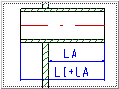
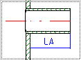
Inserted pipe, flush This function can only be used for hollow bodies. The pipe is inserted through the wall of the vessel and the cut flush to the inner wall. For Length, Outer (LA), enter the required pipe length from the isolated point to the centre point of the connection surface of the outer end of the nozzle. For Length, Inner (LI), enter the distance from the isolated point to the centre point of the face on the inner end of the nozzle that should be cut off. When you specify a value for LI please remember that length specified for the pipe should allow for the thickness and curvature of the vessel wall. The required length L is returned by L = LI + LA. |
|
|
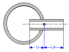
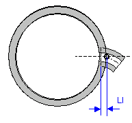
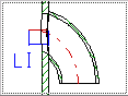
Elbow, mounted This function can be used for hollow and solid bodies. The elbow is mounted on the vessel wall and cut to the outer surface. The vessel wall is bored to match the torus shape of the inside of the elbow. For Length, external (LA), specify the required pipe length from the isolation point to the centre point of the front surface on the inner nozzle end to be cut. Please select a length for LI that ensures that enough material is available to allow for the curve of the vessel wall. You also need to specify the angle of the elbow. You also need to specify an angle value for the elbow – 90° is the default value. The following illustration shows a top view of a cylindrical vessel with a fitted 45° elbow rotated about 90°: |
|
If a straight pipe is used for the nozzle, the following options are available:
- Vertical to bounding surface
- Request alignment
In the example shown above, the option Vertical to bounding surface has been set. If you select Request alignment, you can specify the position of the local CS and change the direction of insertion when you fit the pipe.
Click OK to fit a nozzle. The cursor and the user prompt Identify isolated point on vessel surface appears on your screen.
Fit nozzle
Identify an isolated point on which the nozzle should be set.
If the option Vertical to bounding surface has been selected, HiCAD immediately inserts the nozzle.
With insertion of an elbow, HiCAD halts processing after the pipe has been positioned, and displays the Rotation angle pop-up menu, thus enabling you to turn the elbow about the z-axis. You can now position the next elbow.
If you select Request alignment for an insertion type, the local CS is initially set for vertical alignment, HiCAD halts processing after the pipe has been positioned, and displays a popup menu:
|
|
Move original position to point The position of the Local Coordinate System is restored before the start of the 4th processing step. The CS is then moved (parallel) so that its origin is set on the isolated point. |
|
|
Rotate CS about x The Local Coordinate System is rotated about the x-axis by a given angle. HiCAD expects you to specify an angle. |
|
|
Rotate CS about y The Local Coordinate System is rotated about the y-axis by a given angle. HiCAD expects you to specify an angle. |
|
|
Rotate CS about z The Local Coordinate System is rotated about the z-axis by a given angle. HiCAD expects you to specify an angle. |
|
|
z-axis perpendicular to surface The alignment of the Local Coordinate System is returned to the default setting, i.e. The z-axis is vertical to the vessel wall and points to the interior of the vessel. |
|
|
Rotate CS, z-axis through point The direction of the z-axis of the Local Coordinate System is determined by a point specification and the CS appropriately rotated. |


Please note that a nozzle is always fitted in such a way that its centre line lies on the z-axis. The z-axis needs to point inside the vessel. When the CS has been aligned, click Continue to fit the nozzle. Select Cancel to stop insertion.
In both cases, HiCAD expects you to specify an isolated point. You can now position the next nozzle with the same type of insertion.
 When a nozzle has been fitted, please check several views to make sure that it has been inserted correctly, i.e. that the correct type of insertion was used.
- Open the context menu with a right-click and, if necessary, change the view.
- If insertion was not successful, click Undo.
- Select ESC to exit the menu.
- Select ESC again to return to the selection menu. Select End to exit nozzle insertion.


Fit Nozzle in Vessel (PE) • Part Tools (PE) • Plant Engineering Functions