Simplify > Change > Merge all solids 
Use this function to merge all parts of the type "Solid" that belong to a part list (multiple selection) to one new solid by means of a Boolean operation. Proceed as follows:
- Define the part list, e.g. using the context menu functions in the ICN or the part filters.
- Call the Merge all solids function.
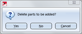
- Specify whether the original solids are to be retained or deleted after merging.
 Please note:
- The newly created solid will automatically obtain the name Part.
-
All non-solids of the part list (e.g. parts with isolated points, parts with free edges (sketches), parts with free surfaces) will not be considered for the merging and will be subordinated to the new solid as individual parts.
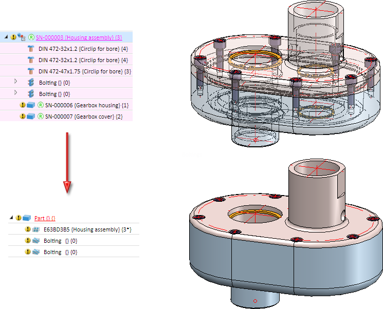
Example:
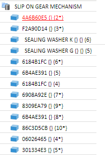
The image below shows a housing assembly. This assembly of the type Part with isolated points contains assembly points. Subordinated to the assembly are various solids and two bolted connections of the type Part with free edges. Subordinated to the bolted connections are the bolts (solids). If you now apply the Merge all solids function to the housing assembly, the new solid will contain the assembly with the isolated points and the bolted connections (without the bolts) as sub-parts.
- If the part list contains no solid, an appropriate message will be displayed and the function will be cancelled.
- If a Boolean merging of the parts is not possible, an appropriate message will be displayed. The original state will then be restored.
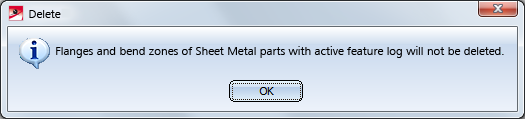
- If the part list contains one single Sheet Metal flange or Sheet Metal bend zone, the single part will be added to the new solid, while the original Sheet Metal part will be retained with the single part. The following message will be displayed:
- If the function will be applied to one individual part, this part will be converted into a solid with the name "Part" (without feature). If there are any sub-parts, these will be considered as well.
- If you have answered the query Delete parts to be added? with Yes, and if the part list contains parts that are located beneath locked parts, these parts cannot be deleted. An appropriate message will be displayed.
- The new solid will be shown in all views, in which at least one of the parts located on the uppermost level of the part list were shown.
- Dimensions, form and positional tolerances, texts and annotations of the parts contained in the part list will not be transferred to the new solid.
A practical example:
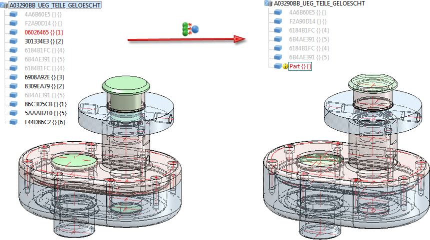
For the sake of a demonstration we will use the example from the Delete Structure Parts topic.
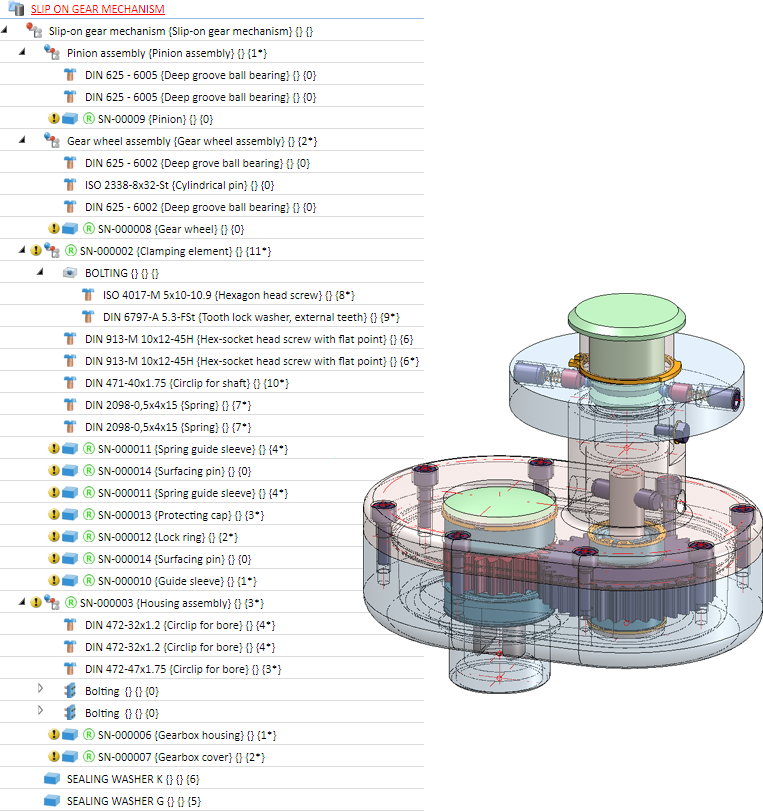
The displayed drawing has been simplified by
- breaking up of the HELiOS links and referencings,
- deleting of the standard parts, and
- deleting of the superordinate parts,
so that all remaining parts are located on the uppermost level.
If you manually hide the "inner" parts, the visible parts can be combined into one solid in one step, so that a simplified / reduced variant of the assembly will be used - for instance, in superordinate assemblies or for an exchange with customers or suppliers.


Identification Modes • Select Parts • Find Parts • Feature (3-D) • Parametric Dimensions (3-D)