Projection Method
The projection is defined by:
- the projection centre (eye or viewer viewpoint),
- the line of vision (line segment between projection centre and spatial centre) and
- the projection plane (screen plane), which lies perpendicular to the line of vision.
In a parallel projection, parallel straight lines are mapped as such and distorted in the same proportion. Engineering axonometry, standard views and isometry are particularly important to the engineering sector.
The projection centre lies at infinity, with all projection rays running parallel to one another and hitting the image plane at the same angle α. If angle α is 90°, this is known as a perpendicular parallel projection; if not, it is known as askew or oblique-parallel projection.
- Central projection
In central projection, also called vanishing point perspective, the distance of the projection centre from the image plane is finite. It takes into account the impression of tapering compared with parallel projection. The proportionateness in the corresponding space direction, typical of parallel projection, is lost due to the converging projection rays. In central projection, object parts which lie in front of the image plane are enlarged, while those lying behind the image plane are reduced. Object parts that lie in the image plane remain undistorted.
The vanishing points of the coordinate axes are also referred to as main vanishing points. Depending on the number of these main vanishing points, three types of central projection are distinguished:
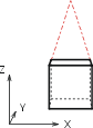
- One-point projection
Two coordinate axes lie parallel to the image plane and hence are projected in parallel onto the image plane. Only the third axis converges on a vanishing point.
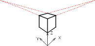
- Two-point projection
Two-point projections are created when the image plane lies parallel to a coordinate axis. In this case, the two other axes converge on a vanishing point.
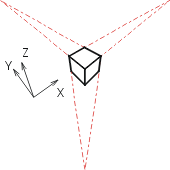
- Three-point projection (general case)
None of the coordinate axes lies parallel to the image plane, but all axes converge on a vanishing point.
You use the Rectangular zoom window >  Factor + point
 ![]() function (View all > RMB) to define the size of the image plane. It is preserved
until such time as you set another size by changing the zoom factor. The
zoom factor generally changes after you call the View
all
function (View all > RMB) to define the size of the image plane. It is preserved
until such time as you set another size by changing the zoom factor. The
zoom factor generally changes after you call the View
all  function. The mentioned zoom functions can be found on the transparent toolbar
 ![]() in the drawing area.
in the drawing area.

