Extruded Solids
3-D Standard > > Extruded solids 
You use this function to create general cylinders. They are derived from closed sketches by moving a copy of the sketch along a normal.
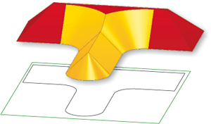
Particular mention deserves the automatic processing of self-intersections. The image below shows an extruded solid derived from a sketch with self-intersection processing. The "oblique" surfaces were created as draughts of the extruded solid; the other, highlighted surfaces would contain self-intersections without an appropriate processing. After self-intersection processing has been applied, they end well below the cover surface and can be extended up to the cover surface via (cut) edges if required.

Recommended procedure:
To create an extruded solid, proceed as follows:
- Enter the Article number.
- Activate the Reference checkbox if you want the extruded solid to be referenced.
- Activate the Feature checkbox if you want a corresponding feature of this extruded solid to be included in the feature log.
- Activate the BOM-relevant checkbox in order to automatically assign this attribute to the created revolved part.
- Choose the type of Height definition.
- Enter, if required, the values for the Draught and the start and end height.
- Choose the type of cross-section definition via the Sketch for cross-section.field. You can create a new sketch or use a sketch that already exists in the drawing.
- If you first want to check what the created part looks like, click the Preview button, followed by Apply if you want the part to be created as displayed. If you want the part to be created directly – without a preview –, click Create.
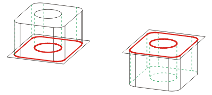
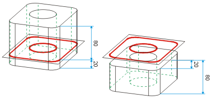
The images below show extruded solids, generated with different values for draughts, start height and end height.


Left: Start/End height: 0/80  Height of part: 80; Right: Start/End height 0/-80
  Height of part: 80

Left: Start/End height: -20/80  Height of part: 100; Right: Start/End height -20/-80
  Height of part: 60

Left: Start/End height: 20/80  Height of part: 60; Right: Start/End height 80/0
  Height of part: 80 (part "inverted")
Please also read the notes on the purposes and representation of sketches.
![]() Please note:
Please note:
- If a Sketch is active when you call the function, this Sketch will be used. .
- If you want to insert extruded solids as sub-parts to the active part, click
 and select Create new extruded part as sub-part
 .
. - It is recommended to apply the Sort
GE (sketch)
 function to sketches first.
 - Circular arcs produce cylindrical surfaces in the analytical model.
- Internal cycles, i.e. closed polylines, circles and ellipses lying within a sketch area, are interpreted as cut-outs/bores.
- The height of the extruded solid as well as HCM dimension conditions assigned to the sketch are taken over as parametric dimensions.
- Circles lying within a surface of the sketch and closed polylines are regarded as bores or cut-outs.
- Clicking
 ... opens a pull-down menu with the functions 2-D -> 3-D Conversion
  und 2-D -> 3-D Level -> Body
  .
. - If the sketch already exists, you can also use the Extruded part from sketch function in the context menu of the sketch to create the extruded part. Please note the following: If the sketch belongs to an assembly, the resulting extruded part will also be assigned to this assembly.

