Right-click 3-D part > Part/assembly structure

Change part - Into main assembly
Converts a dummy part  or an assembly
  to a main assembly
 . This will change the drawing into an assembly drawing! All parts and assemblies that are created afterwards will be assigned to this main assembly.
Change part - Delete main assembly identifier
Converts a main assembly to a normal assembly , removing the main assembly identifier in the process.
Change part - Into assembly
Converts a dummy part to an assembly. First, enter the desired attributes, especially the assembly type and the article number of the assembly, in the Part attributes dialogue window. Sub-parts of the dummy part will then be made sub-parts of the assembly. No assembly main part will be defined in the process.
Change part - Delete assembly identifier
Converts an assembly to a dummy part , removing the assembly identifier in the process.
Change part - Into assembly main part
Into assembly main part 
Converts the active part to an assembly main part. The part will be placed at top position in the assembly. If the active part did not belong to an assembly, an error message will be issued. You will then have the option to create a corresponding assembly. Assembly main parts will be indicated in the ICN by means of the  icon.
icon.
Delete main part identifier
Delete main part identifier 
Use this function to delete the identifier of an assembly main part. . The part will become a "normal" part and the identifier will be removed. This function makes sense in welded Steel Engineering assemblies, where you want to remove the identifier of an assembly main part that was created in the welded assembly.
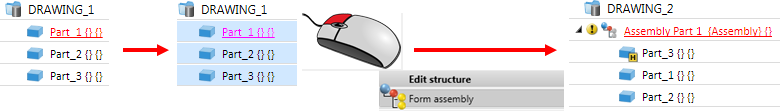
Form assembly
Form assembly 
Assemblies can also been formed using existing 3-D parts and assemblies.
- Right-click the desired part/assembly in the ICN or in the drawing.
A multiple selection of parts/assemblies is also possible: Left-click the desired parts one by one while holding down the CTRL key, then right-click a part/the assembly in your selection to open the context menu for 3-D part.
- Select Form assembly (at Edit structure or Part/Assembly structure).
The following security prompt will be displayed:
Click Yes to continue the function, click No to cancel the function without forming an assembly.
After creation of the assembly, the Part attributes dialogue window will be displayed, allowing you to determine the attributes of the assembly immediately.
The following rules apply to the forming of assemblies:
- If the function is applied to 3-D parts (solid primitives, beams...), all selected parts will be subordinated to new assembly. The part that you right-clicked will be the assembly main part.
- If the function is applied to dummy parts or 3-D sketches, (with sketch geometry) the part that you right-clicked will be converted into an assembly and the following will happen:
- All other selected parts (if any) will be subordinated to this new assembly.
- The sketch geometry will be contained in the assembly
- Planar sketches are handled like 3-D parts (i.e. they will be subordinated and not converted!)
- If the function is applied to a multiple selection (part list) that contains assemblies, the following will happen:
- If the selection consists only of assemblies, the newly formed assembly will have no assembly main part.
- If the selection consists of assemblies and other 3-D parts, the part that you right-clicked (or the first found 3-D part of the selection) will be made the new assembly main part
- The assembly type Assembly will be automatically assigned here.
- In the ICN, assemblies are marked with a
 symbol, assembly main parts with a symbol.
If the active part is a dummy part  , it will be converted into an assembly .
Please note:
As with the creation of an assembly with the 3-D Standard > New > Assembly  function, the Part CS of the assembly can either be automatically determined by HiCAD or manually by yourself. This means that here, too, the parameter Coordinate system for assembly creation in the Configuration Editor at Modelling > Part creation > Assembly will be considered.
 Please also note the information given in the Create New Assembly and Assembly Points and Assembly Article number topics in the HiCAD Basics Help.
Analyze
Checks whether the structure of the current assembly is correct, and whether the assembly has an assembly main part.
Example:
Let us assume that you have inserted a main part with the name "1". You have then assigned a sub-part with the name "2" to this main part. At this point, none of these parts is "BOM-relevant".

Now, make the main part an assembly (right-click and select Part/Assembly structure > Form assembly). A superordinate assembly part will then be created, and the selected main part will automatically become the assembly main part. The position of the sub-part will be preserved.
If you now assign the BOM-relevance attribute to the sub-part, and check the assembly with the Analyze function, HiCAD will issue an error message. Upon automatic correction, the sub-part will be arranged on the same level in the ICN as the main part.
Update
Updates the current assembly, e.g. after structural changes, Copy/Paste actions etc.
Convert
Use this function to change the type of an assembly. HiCAD distinguishes between various types, e.g.
- General assemblies,
- Bolted assemblies (site),
- Welded assemblies (workshop),
- Mullion assemblies,
- Glass assemblies,
etc.

Create Parts and Assemblies (3-D) • Drawing Objects • Model and Process Parts (3-D)