Envelope Parts
![]()
Simplify > Create > Envelope ![]()
This function enables you to protect important drawings and generate simple models rapidly. Simplified representations without internal structures can be created at the push of a button. Such "envelopes" are solids that can be processed further in the target system. At the same time, the use of envelopes reduces the amount of data significantly.
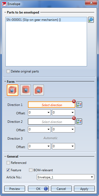
Parts to be enveloped
In this area, parts to be enveloped are listed/selected. After calling the function, the active object will be shown here. This can be a single part, an assembly parts of a part selection or all parts of a drawing. To remove parts from the list, right-click the desired item and select Remove element(s) from list. Multiple selections are also possible.
To add further parts to be enveloped, click the Select part  icon and select the desired parts from the in the ICN or in the drawing. The parts highlighted in the part selection will also highlighted in the drawing (Special colour "Preview"). If you select an already marked part again, the marking will be removed, and the part will be removed from the list.
After selecting all desired parts, press the middle mouse button. This will take you to the next dialogue step, namely, the selection of the axis.
If you want to delete the originals after creation of the envelope, activate the Delete original parts checkbox.
If you select the Translation option beneath Form, the additional Allow holes checkbox will be available. If you activate this checkbox, holes (e.g.bores) in the original will be considered for the envelope as well.
General
Envelopes are solids and can be referenced, processed via their feature, or set to BOM-relevant via the corresponding checkboxes, like all other parts.
By default, HiCAD will enter the name Envelope_n in the Article number field, with n being a consecutive number. If you want to use a different name, overwrite the default entry.
Form
In this area you specify the form and size of the envelope. Concerning the specification of the form, please note the following:
- Click the
 icon to switch to the axis or direction selection at any time.
 - If an axis or direction has been selected, the texts Select axis or Select direction will be replaced with the texts Axis or Direction and the colour of the field will be changed.
- Select a lateral surface of a cylinder or cone to select the cylinder/cone axis. The direction will be determined by the current cursor position.
- When a direction specification via 1st point, straight line or plane for direction (RMB = Further options) is requested, you can right-click to open a context menu with further options:
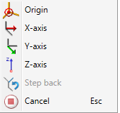
Origin
The start point of the direction vector will be placed in the origin of the active coordinate system.
X-, Y- and Z-axis
The corresponding axis of the active coordinate system will be selected.
Step back
Jumps back one step (if possible).
Cancel
Cancels the functions without creating the envelope.
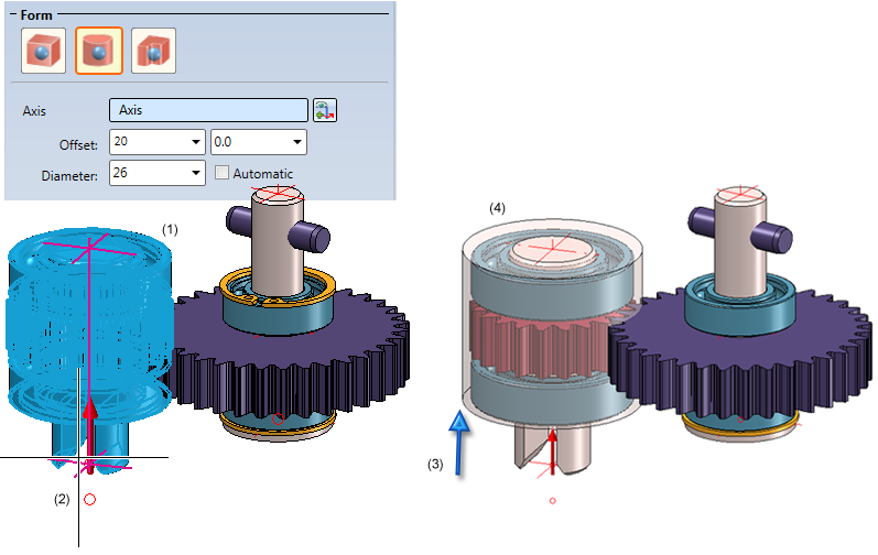
The different options are explained in the following example. The assembly on the left (Pinion assembly) is to be enveloped.
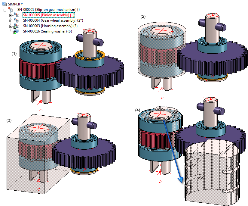
(1) Original, (2) Cylindrical envelope, (3) Bounding box, (4) Translational envelope (in the image the property "Transparent" has been assigned to the created bounding box)
|
|
Cuboid Required data:
|
|
|
Cylinder Required data:
|
|
|
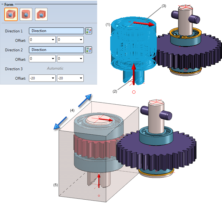
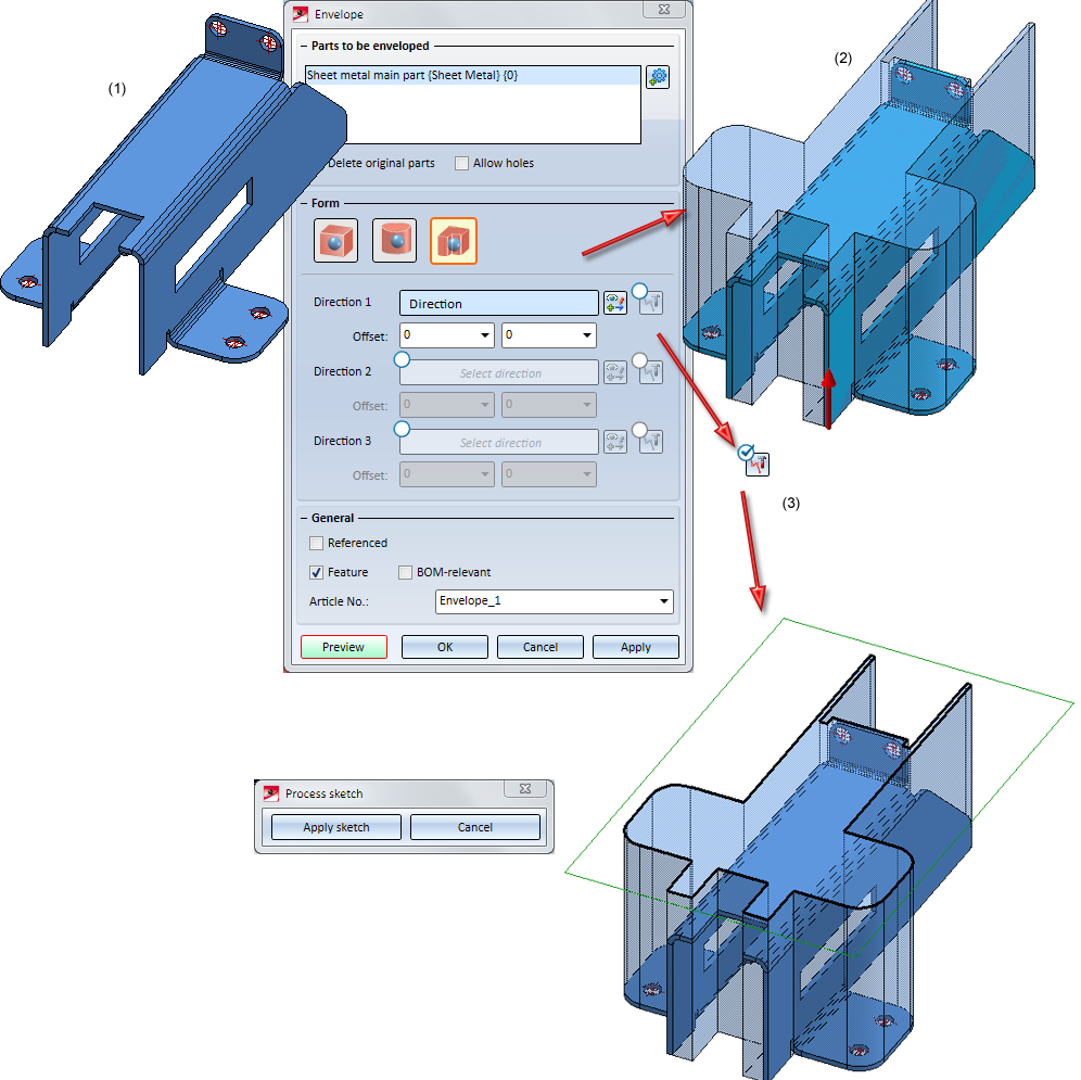
Translation Here you can create translational envelopes in up to 3 directions, the average value of which will then be calculated. Required data:
This direction is the first translation direction. Click the
Here you have the option to specify further directions. To do this, you need to activate the options
For all directions you can specify an offset to change the height of the envelope. HiCAD will first create one envelope for each specified direction and will then calculate their average value. Please note: Here, the additional checkbox Allow holes is available. If you activate this checkbox, holes (e.g.bores) in the original will be considered for the envelope as well.
|
|
|
Manual/automatic - Process sketch For each of the three defined directions you have the option to process the sketch on which the corresponding extruded envelope is based. For this to happen, you first need to click the Preview button. Click the Manual/Automatic
You can now process the sketch with the Sketch functions. After completion of the processing, confirm with Apply sketch. The envelopoe will then be adjusted accordingly.
|


 first. Then, click the
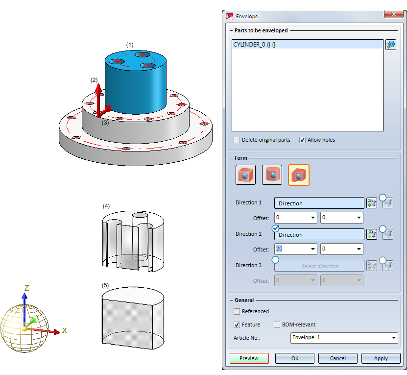
 radio button for the corresponding direction, and then, click the Process sketch
  symbol. The corresponding sketch and the following dialogue window will be displayed:
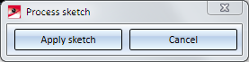
Buttons
After completion of all required input, continue by clicking on one of the following buttons:
|
Preview |
Activates or ends the preview. |
|
OK |
Creates the envelope and closes the dialogue window. |
|
Apply |
Creates the envelope, while the dialogue window remains open. Instead of clicking Apply in the dialogue window, you can also press the middle mouse button (MMB) to apply the envelope. |
|
Cancel |
Closes the dialogue window without creating the envelope. |
 Please note:
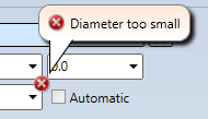
- Incorrect or missing entries will be indicated by the
 symbol. If you move the cursor over the symbol, a corresponding info text will be shown, e.g.:
- If the function cannot be executed with the data you entered, this will be indicated by the
 on the OK button.
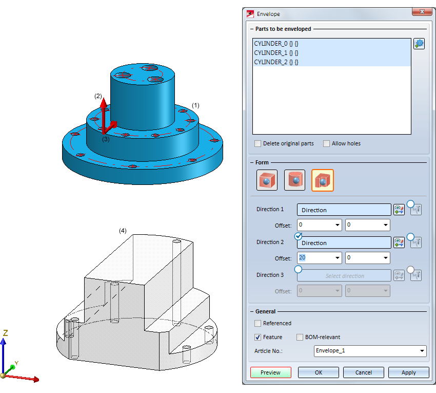
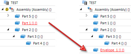
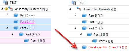
- In the part structure, the envelope will be created on the same level as the selected part; if there are several parts, it will be created on the highest level of the part structure.
If Part 1 is enveloped in the example shown below, the envelope will be located on the same structure level.
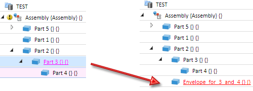
If Parts 3 and 4 are selected, the envelope will be located on the same level as Part 3:
If Part 1 and 2 are selected, the envelope will be located on the same level as Part 1:
- If the Feature checkbox was active during creation of the envelope, the envelope can be changed via its feature log entry:
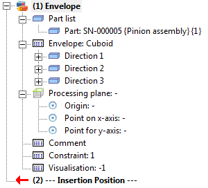
Please note that the envelope will be hidden during processing. It will only be redisplayed after clicking the Preview button.


Identification Modes • Part Selection • Find Parts • Feature (3-D) • Parametric Dimensions (3-D)