Insert Boltings/Rivetings
3-D Standard > Standard Parts > New bolting/riveting 
The dialogue for the insertion of boltings and rivetings begins as soon as you click OK to end one of the tabs of the Bolting dialogue window.
Now proceed as follows:
- Identify the parts that you want to be bolted/riveted together.
- Use the middle mouse button to end the selection.
- The Grid window opens. Choose the fitting type:
|
|
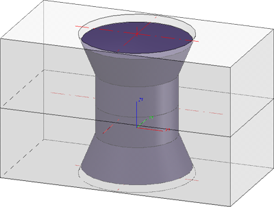
Individual fitting. The bolting/riveting is fitted perpendicularly into the processing plane opposite the z-axis. |
|
|
|
Multiple fitting, linearly arranged |
|
|
|
Multiple fitting, linearly arranged between 2 points |
|
|
|
Multiple fitting, arranged circularly in the fitting plane |


- Enter the required parameters.
- Specify the fitting position. Note that the position of the bolting/riveting depends on the reference plane which you have chosen in the bolting settings!
Left: Fitting point for reference plane: Upper edge, Right: Fitting point for reference plane: Countersink
Bolting on a polar grid
Riveting
 Please note:
- Boltings and Rivetings can now also be inserted repeatedly. This means that the New bolting/riveting function will not be ended automatically after insertion, but remains active, allowing you to insert further boltings or rivetings with the same settings (processing plane, bolting assignment, clamping length etc.). What can be modified, though, is the grid used for insertion.
- The components of a bolting are combined in an assembly called BOLTING, the components of a riveting in an assembly called RIVETED CONNECTION.Whether this assembly will be created as a main assembly or sub-assembly depends on the specified settings for boltings.
- In the centre of the bolting representation (i.e. the BOLTING assembly), an isolated point is created, enabling a direct identification of the bolting. This principle also applies to rivetings.
- Before specifying the fitting position, you can right-click to open a context menu. The functions of this context menu enable you, for example, to change the fitting direction or the reference point of the bolting or riveting.
- When bolting or riveting referenced parts together, the link between bore and bolting or riveting will be removed. In this case an appropriate system message will be issued. When changing the bolting or riveting subsequently you need to adjust the bores manually!
- If the assembly in which the bolting is to be created is locked, the following message will be displayed:
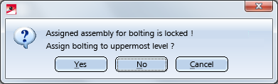
If you select Yes, the bolting will be placed at the uppermost level of the part structure. You can avoid this query by activating the Uppermost level option in the Bolt assignment area of the Settings dialogue window right from the start.
|
Notes on DIN EN 14399 The tables for the bolts according to DIN EN 14399 contain a column called SET for the set identification. If a text, e.g. Set, has been entered there, the nut will not be BOM-relevant when inserting a bolting set according to DIN EN 14399. In this case, the set ID in the Article number will be considered, for the BOM e.g. Set EN 14399...... , as otherwise only the bolt would be supplied. If you clear the SET column in the Catalogue Editor, the nuts will be become BOM-relevant as well. |


Create Boltings (3-D) • Boltings and Rivetings (3-D) • Change Boltings/Rivetings (3-D)