Radius and Diameter Dimensioning
3-D Dimensioning + Text > Individual dimensions
The Diameter dimensions and Radius dimensions functions enable you to create diameter or radius dimensions on circles, spheres, cylinders or tori. of a circle or circular arc. Determine the desired object by selecting an edge or a surface - depending on the settings in the Element type selection, dialogue window.
The following functions are available:

|
Dimensions the diameter of a circle, the radius of a circular arc or the radius of a cylinder, cone, sphere or torus. |

|
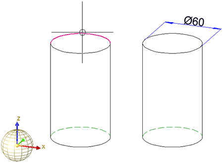
New diameter dimension, axially parallel Axially parallel diameter dimensions. In the case of circles or circular arcs, the dimension line lies in one of the quadrant points. The latter is determined by means of the point specified for the dimension line position. |
|
|
New diameter dimension, free Diameter dimensions with free position of the dimension line. |

|
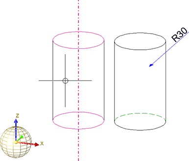
New radius dimension, free Radius dimensions with free position of the dimension line. |

|
New radius dimension, axially parallel Axially parallel radius dimensions. In the case of circles or circular arcs, the dimension line lies in one of the quadrant points. The latter is determined by means of the point specified for the dimension line position. |

![]() Please note:
Please note:
- All functions first require the determining of a circle, a cylinder, a sphere or a torus, followed by the dropping of the dimension.
- Before dropping the dimension you can switch dimensioning plane. To do this, press the right mouse button (END).
- If you fit a bore with a thread as a standard part and apply a diameter dimensioning, these dimensions are automatically created as thread dimensions. In this case, the symbol M (metric thread) is placed in front of the dimension figure, instead of the diameter symbol. If you want to switch off this thread designation and use the diameter symbol instead, change the relevant entry in the Configuration Editor (ISDConfigEditor.exe): Select ... > Drawing > Annotations > Dimensioning, 3-D > Interactive dimensions > ... Dimension figure and deactivate the Thread designation checkbox.
- You can use the mouse
to rotate diameter dimensions about the centre point, and move dimension figures. The dimension will be placed once you have clicked the LMB. The same
applies to parametric dimensions.
The angle grid for the rotation can be specified via the dimensioning parameters, and refers to the dimensioning coordinate system of the original dimensions. To do this, select ... > Drawing > Annotations > Dimensioning, 3-D > Interactive dimensions > ... > Grid > Angle grid and change the value as desired.(Default 7.5).


Dimensioning (3-D) • Dimensioning Procedure (3-D) • Dimensioning, Settings (3-D)