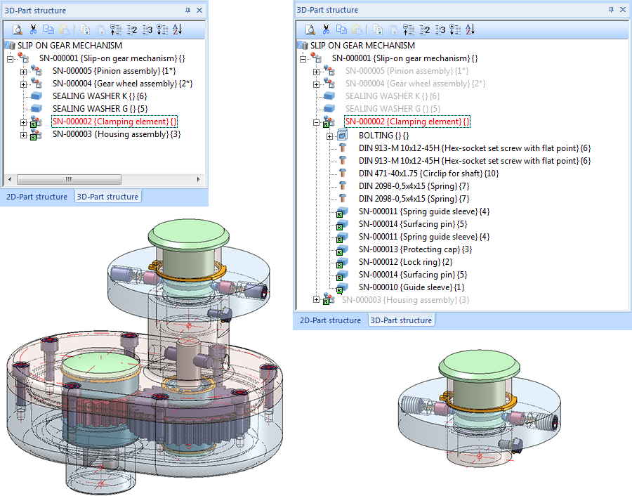
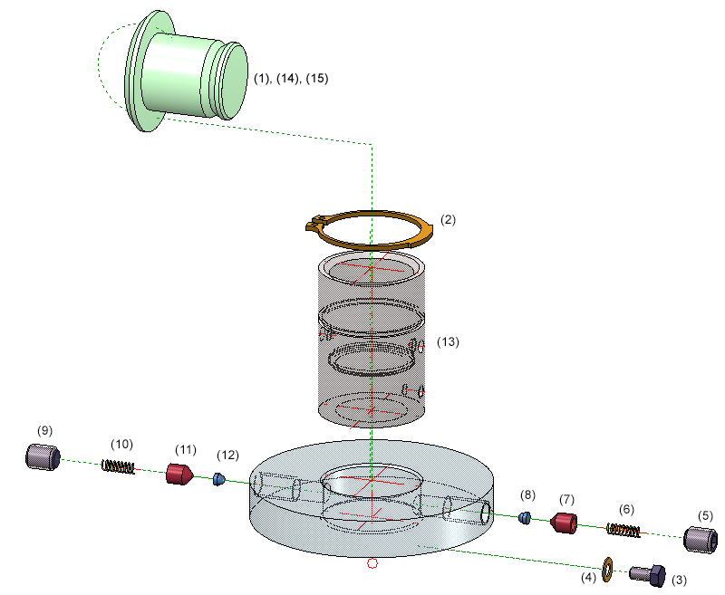
The image below shows a Slip-on gear mechanism. In this example an exploded view of the Clamping element assembly shown on the right hand side is to be created.
Proceed as follows:
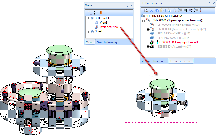
Step 1: Define a view for the exploded representation:
- First, create a new view of the Slip-on gear mechanism, e.g. a view with the name Exploded View.
- In this view, hide all assemblies and parts, except for the Clamping element assembly.
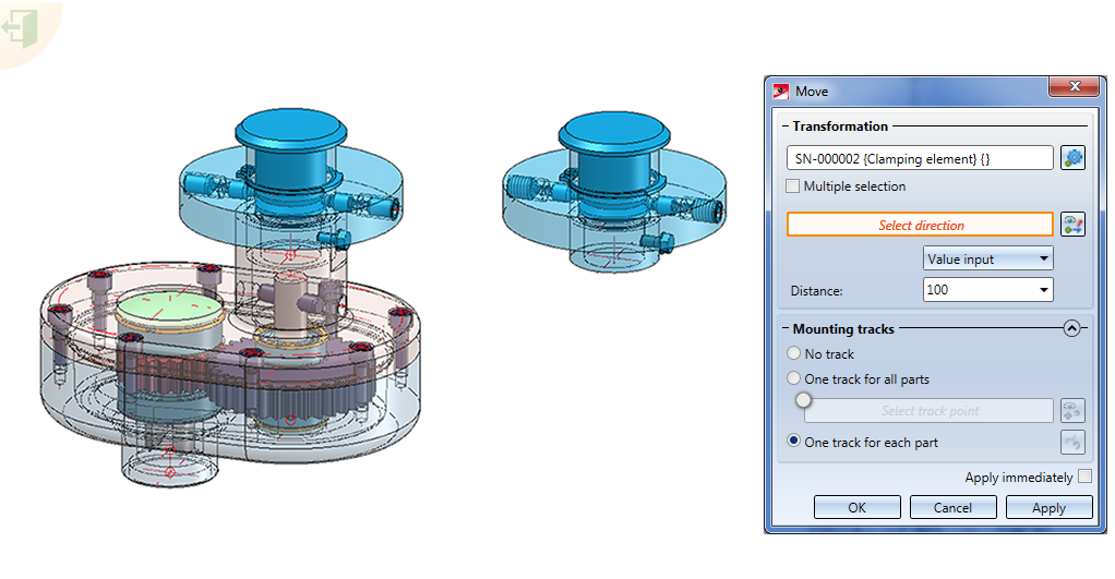
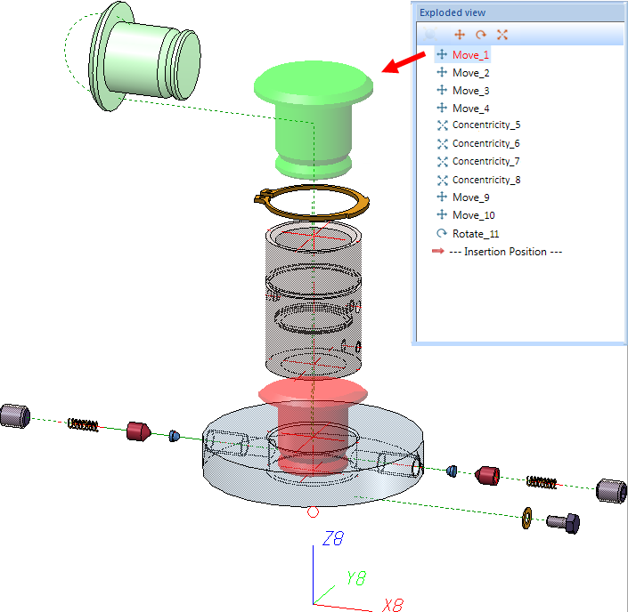
Step 2: Activate Exploded view mode and move elements
- Then, call the Exploded view
 function. HiCAD switches into the Exploded view mode.
- Open the Move dialogue window with a click on the
 Apply the function to the Clamping element. Since you want to transform the individual parts of this element, right-click this entry in the dialogue window and choose Remove element(s) from list.
 - Activate the Multiple selection checkbox.
- Since we want the transformations to be applied only after a clicking the button, deactivate the Apply immediately checkbox.
- To create mounting tracks in the exploded view, also activate the One track for each part checkbox.
- Now you can start defining the transformations of the individual parts.
To close the Move window, click Cancel.
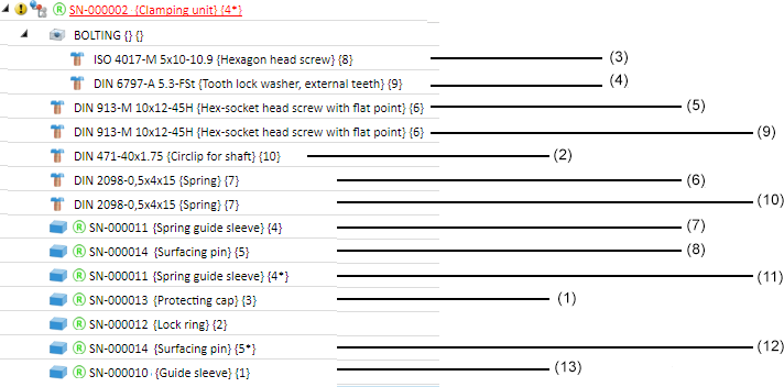
Step 3: Define movements for parts (1) and (2)
- After a click on the
 symbol, select the Protecting cap (3) in the ICN. The movement is to be carried out via Value input with a Distance of 140. Choose the Z-axis (RMT) as direction. When you click Apply the movement will be carried out.
Proceed likewise with the other parts, completing each step with Apply.
- Circlip for shaft (2) , Direction: Z-axis, Distance 110,
- Hexagon head screw(3), Direction: X-axis, Distance 100
- Tooth lock washer(4), Direction: X-axis, Distance 80
Step 4: Define concentricity for the parts (5) and (9), (6) and (10), (7) and (11), (8) and (12)
The hex-socket head screws (5) and (9) are arranged symmetrically to the Z-axis. Therefore, it makes sense to use define the concentricity for these parts. The same applies to the 2 springs, the spring guide sleeves and the surfacing pins. Here, too, we activate the Multiple selection and the One track for each part checkboxes, and deactivate the Apply immediately.
- Hex-socket head screw (5) and (9), Axis: Z-axis, Distance 100 -> Click on Apply
- Spring(6) and (10), Axis: Z-axis, Distance 80 -> Click on Apply
- Spring guide sleeve(7) and (11), Axis: Z-axis, Distance 60 -> Click on Apply
- Surfacing pin(8) and (12), Axis: Z-axis, Distance 50 -> Click on Apply
To close the Concentricity window, click Cancel.
Step 5: Define movements for parts (13) and (1)
- Spring guide sleeve (13), Direction: Z-axis, Distance 75 -> Click on Apply
- Protecting cap (1), Direction: X-axis, Distance -100 -> Click on Apply
To close the Move window, click Cancel.
Step 6: Define rotation for the protecting cap (1)
Now, rotate the protecting cap in the exploded view.
- Click the
 symbol to open the Rotate dialogue window. Choose the Clamping element as the part to be rotated. As you want to rotate only the Protecting cap (15), right-click the entry and choose Remove element from list.
 - Also, activate the Apply immediately checkbox.
- Activate the One track for each part checkbox to create mounting tracks in the exploded view.
- Now you can start rotating the protecting cap. After clicking on the symbol, choose the Protecting cap (1) in the ICN. Carry out the rotation by means of a value input, namely, -90°. To determine the rotation axis, use the quad points shown in the image below.
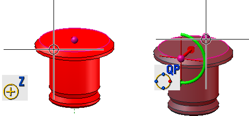
Click Apply to perform the rotation.
Accordingly, the Exploded view docking window will contain 14 displacements and 1 rotation. When you click on a transformation in the exploded view log, the transformed part and also the previous position of the part will be highlighted.
The exploded view creation as film:

