Multiple Insertion via Grid
Most standard parts, standard processings and boltings can be inserted as single or multiple elements (patterns) on a linear, polar or radial grid. Once you have selected the object to be inserted, the Grid menu will be shown.
|
|
Point Insertion of an individual standard part or an individual bolting. The bolt is fitted perpendicularly to the processing plane opposite the z-axis. The reference point lies in the specified fitting position. |
|
|
|
|
|
Multiple insertion , arranged linearly, between 2 points |
|
|
Multiple insertion , arranged circularly in the fitting plane |
|
|
Multiple insertion, arranged radially on a cylinder surface |
![]() During multiple insertions, a preview of the standard part pattern will displayed. If you have changed an input value, press ENTER/ RETURN. The preview image will then be updated immediately.
During multiple insertions, a preview of the standard part pattern will displayed. If you have changed an input value, press ENTER/ RETURN. The preview image will then be updated immediately.
Linear Grid 
The selected standard part is fitted repeatedly. The individual parts are
arranged linearly. In the Linear fitting bar, you define the number of
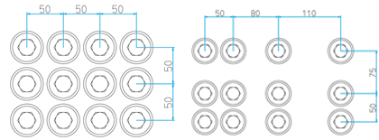
standard parts and their distance from one another.Fitting Point | Specifies the reference point of the standard part pattern. This point is used to position the standard part image, taking into account the selected reference plane (upper edge or countersink). |
nx, ny | Specifies the number of standard parts in x- or y-direction. |
dx, dy | Specifies the spacing of the standard parts in x- or y-direction. You can specify the value individually for each row of the standard part image. |
| Aligns the standard parts equally in x- or y-direction. The spacing of the row/column displayed in field dx or dy is applied to all standard parts in x- or y-direction. |
If you have entered all values, you then specify the fitting position in the drawing.
Linear grid, between 2 points 
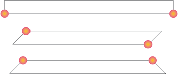
The selected standard part is fitted repeatedly, with the individual parts being arranged linearly on an axis (between 2 points). By this means you can, for instance, insert linear rows of bores along a beam axis. You can select between two procedures - Number and Distance - in the appropriate listbox.
The standard part pattern is aligned by means of an axis which is determined by two points. If the active part is a beam, The Axis area provides the following, additional options:
- Free axis
Use this option to define an arbitrary axis by specification of two points. - Beam axis
Use this option to specify two points which are then projected onto the beam axis. - Smallest length
When you select this option, HiCAD determines the axis automatically. HiCAD automatically uses the points at those beam ends adding up to the smallest possible beam length. This option can, for instance, be useful in case of diagonally trimmed beams.
The Axis field is unavailable for other 3-D parts.
Number
Use this procedure to fit a given number of standard parts. The grid distance, i.e. the distance between two standard parts, is calculated by HiCAD automatically. The following entries are possible:
nx | Number of standard parts |
Edge dist. | The edge distance, i.e. the distance of the fitting point of the first, resp. last standard part to the specified start, resp. end point of the axis. |
In the field L, HiCAD shows the length of the entire bore row. The distance between the standard parts (i.e. between their fitting points) is shown in the dx field.
Distance
Use this function to specify the maximum grid distance. HiCAD automatically calculates the number of standard parts. You can increase/decrease the number by a positive/negative value, if there are - taking the required maximum distance and the specified edge distance into account - no collisions.
Max. | Maximum distance between the individual standard parts |
Add. | Value by which the calculated number of standard parts can (if possible) automatically be increased/decreased. You can enter positive as well as negative values in this field. |
Edge dist. | Distance of the fitting point of the first, resp. last standard part in the row to the start, resp. end point of the axis. |
In the field L, HiCAD shows the length of the entire bore row. The field nx shows the calculated number of standard parts, the field dx shows the distance between the standard parts.
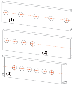
(1) beam axis, (2) free axis, (3) Smallest length
X-direction of the grid for beams is always the direction of the beam axis; otherwise it is the X-direction of the active processing plane.
 If the start point and the end point have the same position in X-direction, HiCAD will issue an appropriate message, informing you that the distance in fitting direction (X-axis) is too small. You can then re-determine the points. This also means that the fitting of bores/standard parts with the Linear grid option is only performed in X-direction of the active coordinate system. If you want the bores/standard parts to run in a different direction, you need to re-define the processing plane, and thus the X-direction.
Polar Grid 
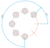
The selected standard part is fitted repeatedly. The individual parts are arranged circularly. The fitting point is the midpoint of the circle.
Enter the required parameters:
n | Number of standard parts |
d | Diameter of the circle |
sa, aa | Start angle and aperture angle |
If you have entered all values, you then specify the fitting position in the drawing.
Radial Grid 
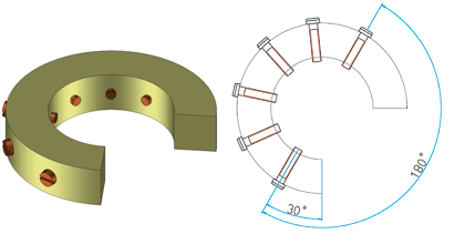
The selected standard part is fitted repeatedly. The individual parts are arranged circularly on a cylinder surface. The fitting point here is always the midpoint of the circle.
Identify the cylinder surface and enter the required parameters:
n | Number of standard parts |
sa, aa | Start angle and aperture angle |
If you have entered all values, you then specify the fitting position in the drawing.


