
Project: HiCAD 2-D
2-D Dimensioning + Text > Surface/Tolerances >Characters
Surface Characters are used to identify requirements on the surface condition of parts. For example, they provide information about the processing method, the required roughness and so on.
Surface characters consist of a graphic symbol for specifying the surface condition and additional text details for further surface parameters.
If you want to assign a surface character to a part, you activate the Characters function (left-click). The Surface specifications window will be displayed.
If you press the right instead of the left mouse button, you can create a leader line (with or without arrow) for the surface character.
(1) Line
(2) Reference point
Parameters
The surface character is completed by the various surface parameters. To ensure the uniqueness of a requirement on the surface condition, you may also need to specify additional number values or other characteristics in many cases.
a Roughness or degree of roughness (N1 to N12), with a1 being the maximum value and a2 the minimum value.
b Production methods, handling, layering or other requirements on the production process for creating the surface
c Requirements on the surface condition
d Surface grooves and alignment, e.g. =, X, M etc.
e Processing allowance as a numerical value in mm
Symbols
|
|
Basic symbol for specifying the surface condition |
|
|
|
Enhanced graphic symbol, material removal is required |
|
|
|
Enhanced graphic symbol, material removal prohibited |
|
|
|
A circle is added to the current symbol. |
|
Orientation
Use the Orientation buttons to determine the position of the character.
Line end symbol
Use this function to specify you want to draw the leader line of the surface character with or without an arrow. After selecting a reference point, you can
Save and Load Favourites
The current settings for surface specifications can be saved as Favourites and reused at any time.
 to save.
 The settings are saved in a file with the specified name and the file extension .SSY to the HiCAD SYS subdirectory.
To load saved settings, select the required file name in the list box beneath Favourites. The names of all SSY files that exist in HiCAD are displayed.
The SURFSYM.INI file
In connection with the surface characters the system file surfsym.ini in the HiCAD SYS directory plays an important role.
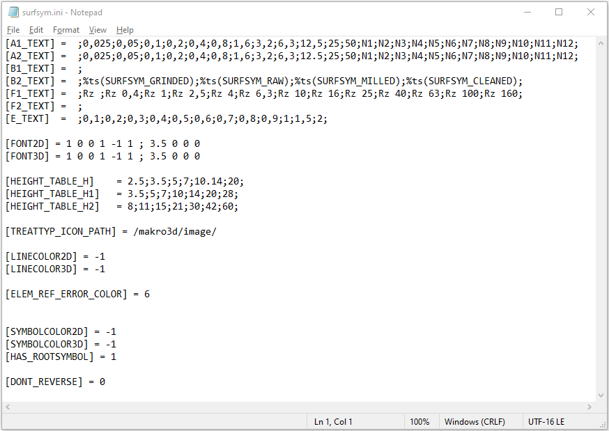
This file has the following purposes:
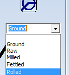
For instance, if you expand the line B2_TEXT by "Rolled", this new entry can then be chosen from the selection box.
[B2_TEXT] = ;%ts(SURFSYM_GRINDED);%ts(SURFSYM_RAW);%ts(SURFSYM_MILLED);%ts(SURFSYM_CLEANED);Rolled
HiCAD uses the keyword %ts to gain access to the internal text service. This will not be required for your own additions, though.
 > Settings
  .
. 

Process Surface Characters (2-D) • Dimensioning (2-D)
|
© Copyright 1994-2020, ISD Software und Systeme GmbH |
Data protection • Terms and Conditions • Cookies • Contact • Legal notes and Disclaimer


