
Project: HiCAD 2-D
The dimension parameter settings on the following tabs determine how the dimensioning is structured:
Once you have made the settings you require, click OK to exit the window.
The prompt: Change all parameters? appears. If you answer YES, all the current parameter window settings are applied; if you answer NO, only the parameters you have changed are applied.
In the Dimension lines/terminations tab, you set all dimension line or projection line parameters such as colour, length or spacing.
Colour
You change the colour of the lines by clicking the new colour. The colour selection enables you to show and hide dimension lines.
Dimension terminations
The dimension termination can be marked by an arrow, circle or forward slash. You can also hide the dimension terminations.
Projection lines
You can enter different values for the two projection lines, e.g. for the length, or the distance to the geometry. The projection lines can be hidden separately.
Length of the projection line 5 mm
Distance means the distance from the geometry (dimension base point) to the start point of the projection line.
(1) Dimension base point with 5 mm distance from the projection line
Projection line excess length
Specify the protruding part of the projection lines in mm.
(1) Excess length of the projection line
Radius dimensions
You specify the minimum length to lengthen the dimension line for small radii beyond the midpoint. You specify the maximum length to shorten the dimension line for large radii from the midpoint.
(1) Lengthening of the dimension line
(2) Shortening of the dimension line
The second tab refers to the dimension figure. Here, you define the display and properties of the dimension figure, such as
Additional texts can be assigned to the dimension figure. In the Dimension text tab, you define whether you want these additional texts to be displayed and specify the properties of the additional texts. These properties are:
This tab refers to the tolerance and fit parameters:
Default value:
Tolerance unit: None
Annotation height: 3.5
Position with respect to dimension figure parallel to the dimension line (1): 1.5
Position with respect to dimension figure perpendicular to the dimension line with the 1st tolerance (2): 5.0
Position with respect to dimension figure perpendicular to the dimension line with the 2nd tolerance (3): 0.0
(1) Parallel distance from the base point of the dimension
figure to the tolerance
(2) Distance from base point of the dimension figure to the 1st tolerance
(3) Distance from base point of the dimension figure to the 2nd tolerance
 Please note:
Changes made in the Position ref. to dim. figure perpendicular to dim. line area of the Dimension parameters dialogue (2-D Dimensioning + Text > Edit > Dimensioning settings > Parameters - Change) will only be preserved if a corresponding tolerance has been defined for the 2-D dimension. For new tolerances, the default settings will be applied.
The first three tolerances correspond to the three upper buttons in the Tolerances dialogue that you can call via 2-D Dimensioning + Text > Edit > Aux.text  > Tolerances. The fourth tolerance corresponds to the three buttons in the second row in the dialogue.
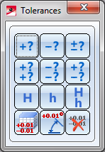
Tolerances menu
Dimensioning symbols, such as the diameter symbol, can be assigned to each dimensioning. In this tab, you define the size of the symbols and their position with respect to dimension figure and dimension line

|
© Copyright 1994-2020, ISD Software und Systeme GmbH |
Data protection • Terms and Conditions • Cookies • Contact • Legal notes and Disclaimer