Project: HiCAD Steel Engineering
Steel Eng. Connections + Variants > Catalogue > Connections
This description applies to the following Design Variants:
A Steel Engineering connection based on a Design Variant is always linked to the Configuration (UDC) with which it was fitted. Internally, this connection is established by assigning the name of the configuration to the parameter variable udc_identifier. Please note that an unexpected behaviour of the function may result from this linkage if the user does not know the difference between the referenced and the non-referenced working with the catalogue system.
Example:
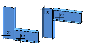
Let us assume that you want to connect the two left beams, as well as the two right beams in the image below, using a purlin joint with 1 plate and mitre cut (201_2).

Call the connection function and identify the two beams on the right hand side. In the dialogue window, create a copy of the _TemplateReferenced template, e.g. Purlin_201_2_ref. Then set the plate projections to 0 and exit the window with OK. The connection is fitted. The connection function remains active.
Now identify the two beams on the right hand side. In the dialogue window, use the previously created configuration Purlin_201_2_ref and change the plate projections to 30. Exit the dialogue window with OK. The connection is fitted. End the function with a right-click.
If you now update the right purlin joint that was fitted first, its plate projections will be set to 30 as well.
This means that if you have fitted a connection with a referenced template several times and then change one of these connections, all connections fitted with this template will be changed in the same way when you update them. To circumvent this automatism, you would have to create another template with different values during referenced designing.
On the one hand, referenced designing enables an easy and convenient synchronisation of connections, but on the other hand it requires a well-planned designing process.
Call the connection function and identify the two beams on the right hand side. In the dialogue window, create a copy of the _TemplateNonReferenced template, e.g. Purlin_201_2_nonref. Change the plate projections to 0 and exit the window with OK.The connection is fitted. The connection function remains active.
Now connect the two beams on the left hand side. Use the previously created configuration Purlin_201_2_nonref . Change the plate thickness and set the plate projections to 30. Exit the dialogue window with OK. The connection is fitted. End the function with a right-click.
If you now update the right purlin joint that was fitted first, it will remain unchanged.

Variants + Connections (3-D SE) • Insert Connections - Procedure (3-D SE) • Dialogue Window for Connections (3-D SE)
|
© Copyright 1994-2019, ISD Software und Systeme GmbH |