Project: HiCAD Steel Engineering
Civil Engineering functions > Steel Engineering > General > Cam joint (2104)
In practice, so-called cam joints are used for a quick positioning and welding of sheets. The 2104 Design Variant enables you to conveniently connect two base sheets with each other.
The respective design variant for Steel Engineering plates can be found in the Civil Engineering functions docking window under Steel Engineering > General.
Please note that both Steel Engineering plates (or their projections) must have a common intersection point.
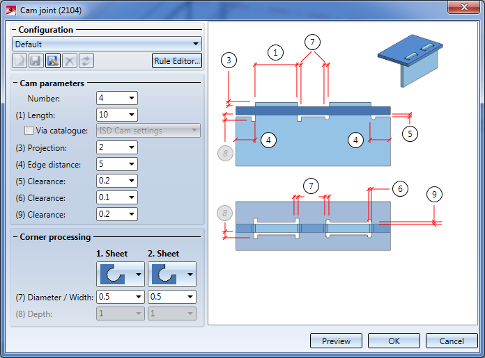
If the connection is not possible due to the selection, a respective report will be displayed. Otherwise the Cam joint (2104) dialogue window will be displayed:
The configuration of the Cam Joint is done via the parameters in the dialogue window.
By clicking on Preview, you receive a preview of the connection - based on the currently entered data. If you want to modify the data, make the respective changes and once more click on Preview to update the preview. With OK you install the connection according to the current data and the dialogue window will be closed. If you leave the dialogue window by clicking Cancel, the function will be closed without installing or changing the connection.

Configurations for connections can be saved in order to access specific configurations right away.
Enter the desired cam joint parameters.
Select the corner processings and enter the required parameters for the selected version, e.g. diameter for the tangential radius.
The following corner processings are available:
|
Corner processings |
Available for |
Entries |
||
|---|---|---|---|---|
|
Plate 1 |
Plate 2 |
|||
|
|
No corner processing |
|
|
None |
|
|
Bore out |
|
|
Diameter |
|
|
Cut out radius tangentially |
|
|
Radius |
|
|
Cut out rectangle |
|
|
Width and depth |
|
|
Cut out slot shape |
|
none |
|
If you have entered all required data the cam joint can be installed. When selecting Preview the cam joint will be installed, but the dialogue window will remain open - in contrast to OK. You can still change data and check the drawing with Preview. If you leave the dialogue window with Cancel, the function will be closed without installing or changing the connection.
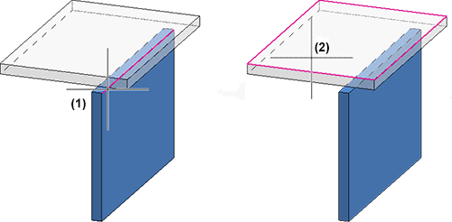
Example:
The two displayed Steel Engineering plates shall be connected. To do so, the outer edge (1) of the first plate will be selected as well as the surface (2) of the second plate.
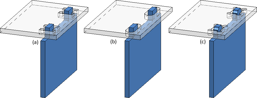
(a): Corner processing 1st and 2nd plate: subtract rectangle
(b) Corner processing 1st plate: none, 2nd plate: slot shape
(c) Corner processing 1st and 2nd plate: Bore out
![]() Please note:
Please note:

Connections and Variants (3-D SE) • Dialogue Window for Connections - Type I (3-D SE) • The Catalogue System for Connections + Variants (3-D SE)
|
© Copyright 1994-2019, ISD Software und Systeme GmbH |


