Project: HiCAD Steel Engineering
"Civil Engineering functions" docking window > Steel Engineering > General > Purlin joint (1206)
Use this Design Variant to bolt one girder and one purlin together, using a maximum of 4 bolts. For additional reinforcement you can insert up to 3 stiffeners on the purlin and the girder.
(1) Original, (2) Purlin joint with 3 stiffeners on girder and purlin

Configurations for purlin joints can be saved, which enables you to access your individual configurations at any time afterwards.
The purlin joint is configured via the tabs of the dialogue window.
Selected parts
On this tab, information on the previously identified beams is displayed, e.g. type, material, dimensions etc. Data input or changes are not possible here.
Geometry
On this tab you specify the dimensions of the purlin joint. These refer to the boltings and the distances between the stiffeners.
Possible are up to 2 bore rows on girder and purlin. Select the desired number of bore rows from the corresponding list box. The value (1) determines the distance of the bolts to the purlin axis, the value (2) determines the distance of the bolts to the girder axis. If there are more than 1 bore rows you can additionally specify an offset (5) of the bolting relative to the purlin axis. The value (3) and (4) determine the distance between the stiffeners on the girder and the purlin.

(a) Purlin, (b) Girder, (c) Top view
If the tracing dimensions of the purlin or the girder (in case of metal profiles: the distances of the rivet rows in web or flange to particular edges of the cross-section) are to be considered, select this option from the corresponding listbox.
 The way in which the distances between the stiffeners is considered depends on the setting selected on the Stiffeners tab.
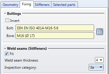
Fixing
The fixing on the target part takes place by means of boltings.
Click the  symbol to select the bolts and bores directly from a standard part catalogue. If you want to reverse the direction of the bolting, activate the Invert checkbox.
The stiffeners are welded onto the purlin or the girder. If you want to insert weld seams, activate the checkbox and enter the seam thickness.
Stiffeners
Up to 3 stiffeners can be inserted on the purlin and on the girder. To do this, activate the Insert checkbox. For each stiffener you can specify the edge to be relevant for insertion: Front side, back side or middle. The distance entered on the Geometry tab will then be used for the settings that you specify here. One example: Let us assume that you insert three stiffeners and select Middle, Back side, Front side. On the Geometry tab you have selected a distance of 75. The stiffeners will then be inserted in such a way that the distance from the back side of the second stiffener to the middle of the first stiffener, and the distance from the front side of the third stiffener to the back side of the second stiffener will have the specified value.
Click the symbol to select the plate for the stiffener directly from a standard part catalogue. In the Type area you can specify via the corresponding radio buttons whether you want to insert a full stiffener of a partial stiffener.
Click the Preview button if you want to display a preview of the connection based on the currently entered data. If you want to modify the current data, apply the required changes and click Preview again to update the preview. Click OK to insert the connection according to the current data and close the dialogue window. If you click the Cancel button, the window will be closed, and the specified or changed connection will not be inserted.
The stiffeners will be assigned to the corresponding beam, the bolting will be assigned to the purlin.

Connections + Variants (3-D SE) • Dialogue Window foe Connections - Type I (3-D SE) • The Catalogue System for Connections + Variants (3-D SE)
|
© Copyright 1994-2019, ISD Software und Systeme GmbH |