Project: HiCAD Steel Engineering
Multi-Storey Stairs + Railings with Equidistant Posts
Civil Engineering functions docking window > Steel Engineering >Stairs + Railings > Railing > Railing Configurator (Railings along beams)
A frequent case in practice is the placing of railings onto multi-storey staircases with equidistant posts. All posts are to be located below one another (with regard to the storey), and parallel to one another (with regard to the staircase sections), respectively. Here, the post configuration in the Railing Configuration) dialogue window will play an important role.
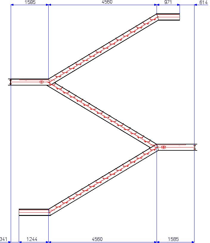
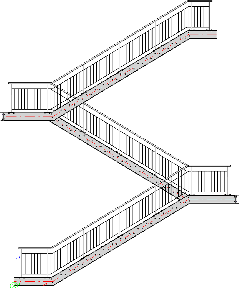
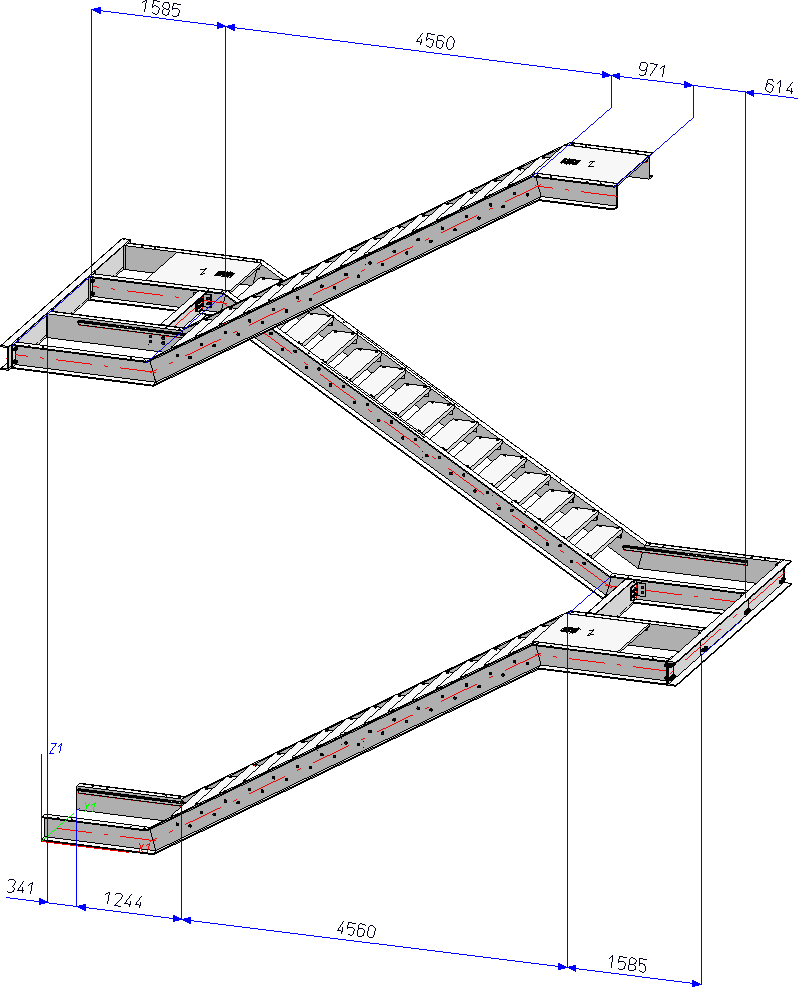
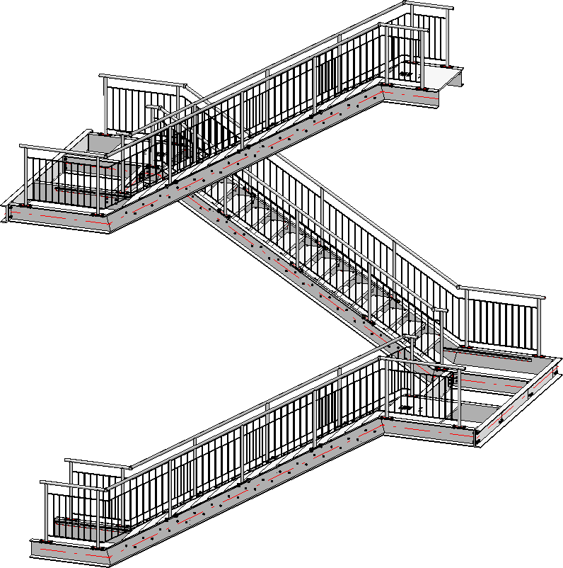
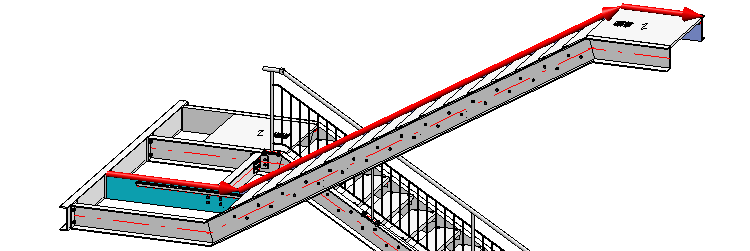
This will be illustrated by means of the following example of a multi-storey staircase.
A railing is to be mounted to this staircase as shown below:
Important:
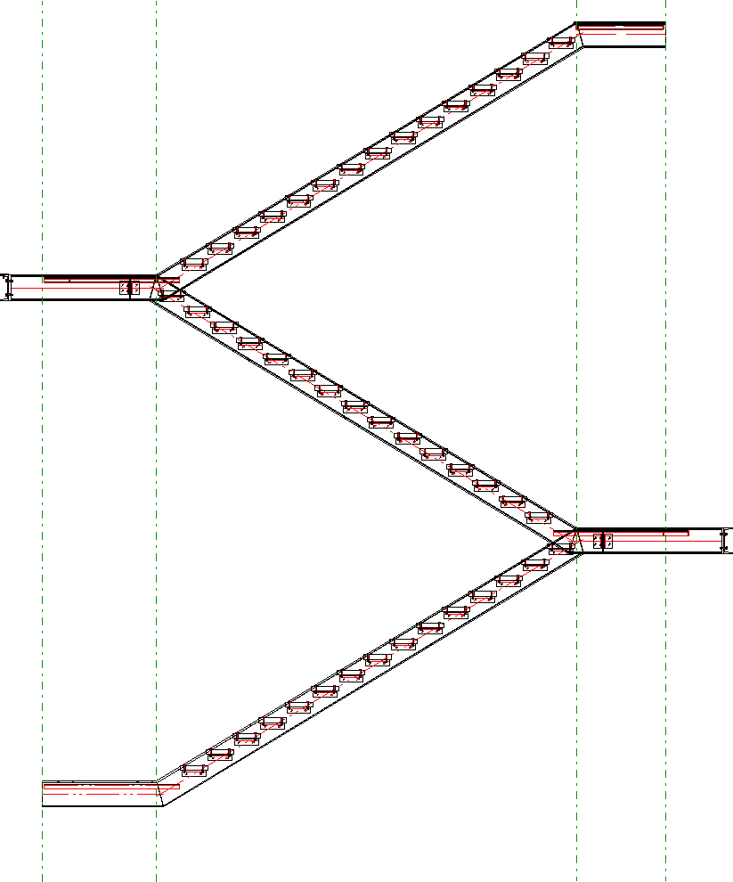
During configuration of the staircase you already need to have a rough idea of what the railing will look like. If the posts of the railing are to be located perpendicular below one another, the transitions (inflexion points) of the walking lines of the staircase must be located one above another.
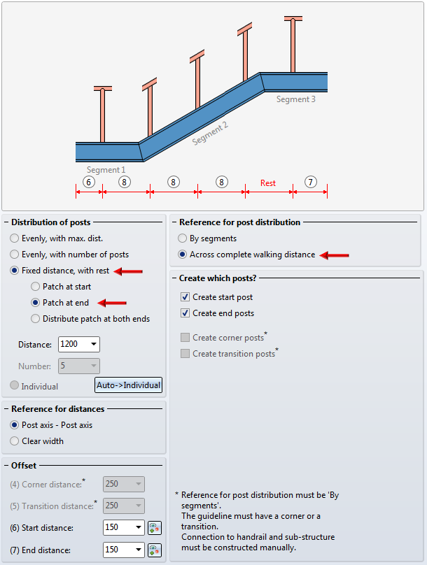
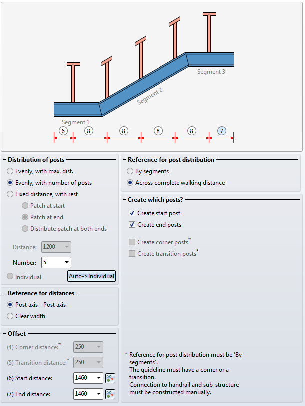
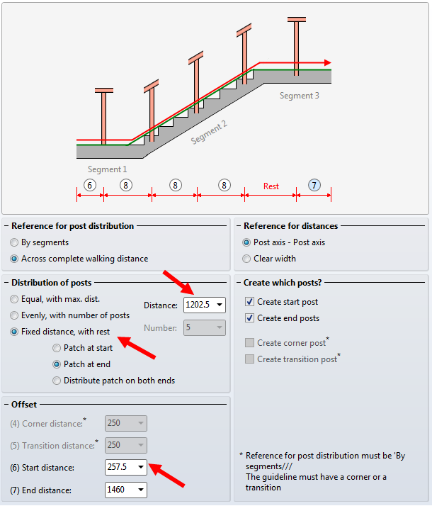
For this example, the settings on the Post distribution tab of the Railing Configurator dialogue window playa crucial role. For the easiest handling you should not work with maximum post distances, but use the other options instead. Furthermore, the distribution of posts should not take place by segments, but across the entire area. The Dimensions 4 and 5 (Corner distance and Transition distance) will therefore not be evaluated in this example.
Evenly, with number of posts
Here, the calculation length will be divided by the number of posts, with regard to the axis. The value in the Distance field as well as the Transition distance (Dimension 5) will not be considered.
Fixed distance, with rest / Position of patches
If you select this option, you need to check whether the remaining rests (patches) are to be located at the start, at the end or on both sides. It is therefore recommended to use "virtual" vertical auxiliary lines during the construction process. For if the railing posts are to be located below one another after completion of the construction, this can be achieved easiest with this option. This means that the specified dimensions will only be used for the active flight of stairs (walking line). In the sketch you can see that the flight of stairs 1 places Dimension 6 at the bottom right (at the start), and Dimension 7 at the left. When you activate the flight of stairs 2, Dimension 6 will be located on the left, and Dimension 7 on the right. This should be taken into account to ensure that the correct distances will be entered. Dimension 5 will not be considered.
When selecting the beams, please note that HiCAD interprets the first selected beam as the start, which the later partitioning of the railing will be based on (fixed distance with rest at the start or end). In practice, engineers mostly use an upstairs walking direction as an orientation.
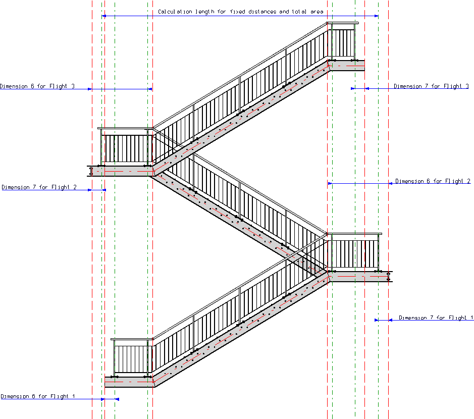
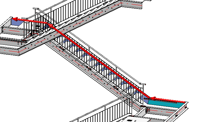
The present example consists of 3 staircase sections (Flight1 to 3). For each flight, the railing will be created separately for the right and for the left stair stringer. This means that railing creation in this example will consist of 6 steps.
The railing creation begins on the left stringer of the 2nd staircase, which is the staircase with the shortest flight. The post distances of the corresponding railing are to be used for all other railings. After creation of the first railing, all other railings can be derived very easily from its data.
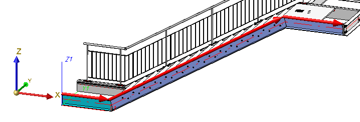
Step 1: Railing for Staircase 2, left stringer
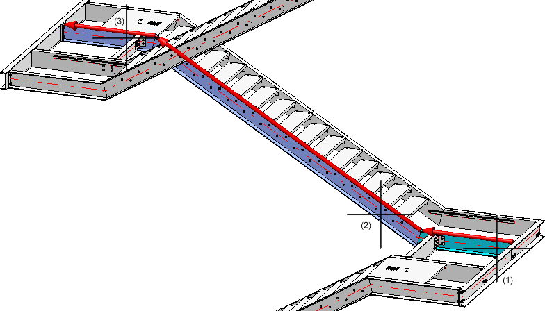
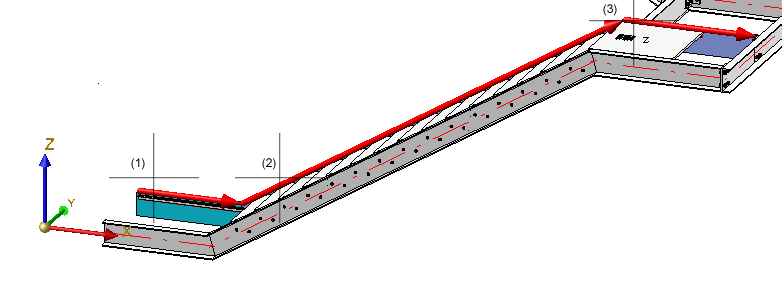
- Call the Railing Configurator. Select beams (1) to (3), so that the walking line will be displayed as shown below. End the selection by pressing the middle mouse button.
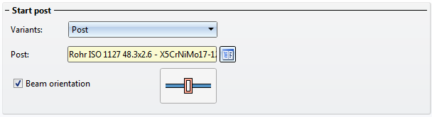
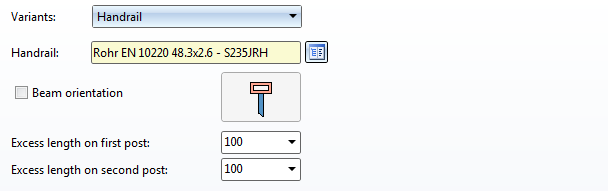
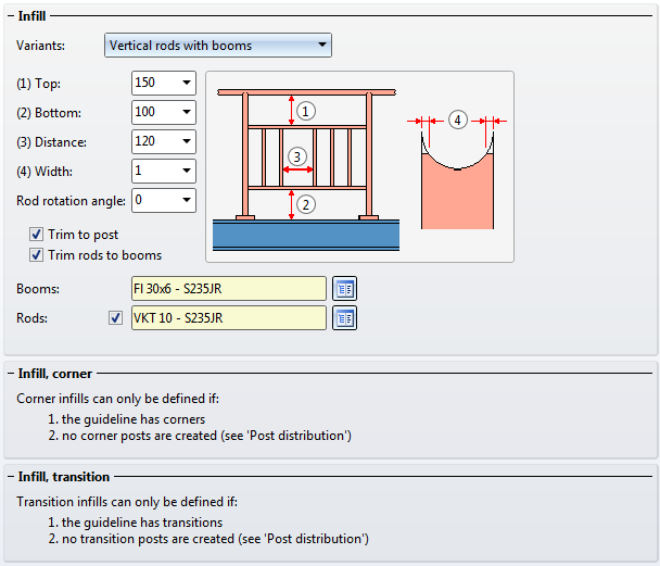
- As the ISD default settings with the exception of the post configuration will be used in this example, load these settings via the Favourites management
 .
.
- Now change the parameters as follows:
- Offset
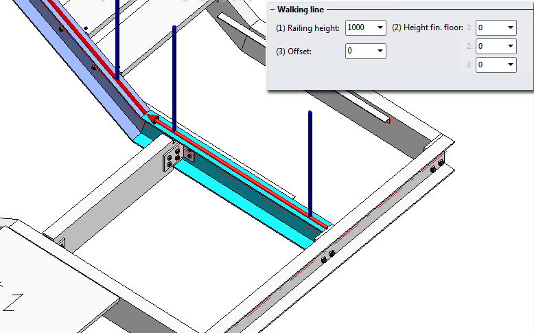
The railing is to be placed in a centred position onto the stringer, i.e.the walking line must be displaced. For this to happen, open the Walking line tab ad enter the value 0 in the Offset input field. In the preview you can see that the walking line is now located in the centre of the upper baem side.
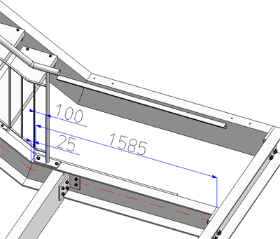
- Start distance (6) and End distance (7)
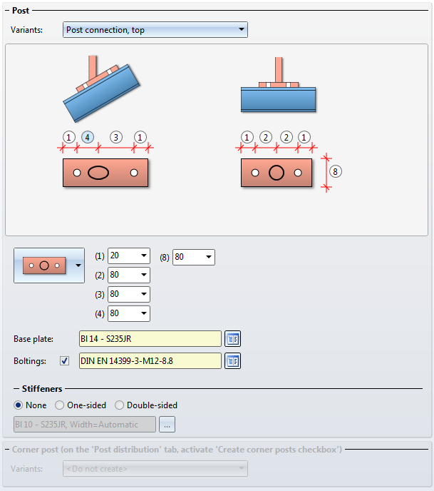
In this example, the start distance and the end distance are to be equal. Select 1460. The reason for this value is as follows: The length of the beam is 1585; for the mounting of the posts to the substructure you use the ISD default settings, i.e. a base plate with a length of 200 on which the post stands with a centred position (i.e. the distance of the post axis to the edge of the base plate is 100). To achieve a proper fixing of the plate, a distance of the base plate to the beam end of 25 must be taken into account. The final result is a start/end distance of 1585 - 100 - 25 = 1460.
- Post distribution
Apply the following settings:
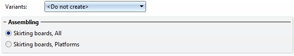
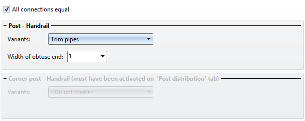
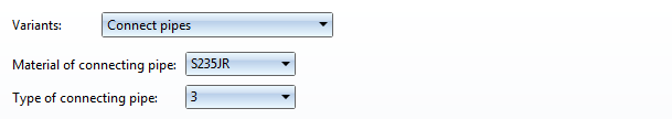
- Specify the components and connections.
- Confirm with OK.
All other railings can now be easily derived from the railing created in Step 1.
Step 2 - Staircase 1, left stringer
- Call the Railing Configurator. Select the beams in such a way that the walking line will be displayed as shown below. End the selection by pressing the middle mouse button.
- The railing parameters set during Step 1 still apply. As the beam types of all staircases are the same, you only need to change the start distance to 257,5. The End distance (Dimension 7) is identical to the Start distance (Dimension 6) of the railing created in step 1, i.e. 1460.
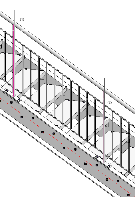
The post distances of the railing is to be the same as the one for the railing created in Step 1, i.e. a fixed post distance must be selected. Click the  symbol to open the Configure post distances dialogue window. There, select the Fixed distance, with rest option. To apply the post distances of the first railing, right-click the Distance field, select Pick distance, and then select the Distance between 2 edges
  option in the menu. Then, identify two neighbouring posts of the first railing in the drawing (1202,5).
- Close the dialogue window with OK. Then, close the Railing Configurator with OK.
Step 3: Staircase 3, left stringer
- Call the Railing Configurator again. Select the beams in such a way that the walking line will be displayed as shown below. End the selection by pressing the middle mouse button.
- The railing parameters set during Step 2 still apply. Now we need to change the settings on the Post distribution tab.
- The start of this railing is to be located at the same height as the end of the railing created in Step 1. This means that here, the start distance is identical to the end distance from Step 1, i.e. 1460.
- The end distance is identical to the end distance of the railing created in Step 2, i.e. 257.5.
- As the posts are to be positioned perpendicular above one another, the rest piece ("patch") need to be placed at the end here. Therefore, select the Patch at end option.
- Close the dialogue window with OK. Then, close the Railing Configurator with OK.
Step 4: Staircase 2, right stringer
- Call the Railing Configurator again. Select the beams in such a way that the walking line will be displayed as shown below. End the selection by pressing the middle mouse button.
- The railing parameters set during Step 3 still apply.
- On the Post distribution tab, set the Start distance and the End distance to 257.5.
- The displayed walking line is located on the inner side of the beam. However, the railing is to be placed in centred position.
- As the posts are to be positioned perpendicular above one another, the rest piece ("patch") needs to be placed at the end here. This option is still active from the previous step.
- Close the Railing Configurator with OK.
Step 5: Staircase 1, right stringer
- Call the Railing Configurator again. Select the beams in such a way that the walking line will be displayed as shown below. End the selection by pressing the middle mouse button.
- The railing parameters set during Step 4 still apply. Open the Post distribution tab.
- The start distance is identical to that of the railing on the left stringer. The end distance is identical to that of the railing created in Step 4, i.e. in both cases 257,5 (value is still set). As the posts are all positioned perpendicular above one another, the rest piece ("patch") needs to be placed at the start here (as with the left stringer from Step 2). Therefore, select the Patch at startoption.
- Close the dialogue window with OK. Then, close the Railing Configurator with OK.
Step 6: Staircase 3, right stringer
- Call the Railing Configurator again. Select the beams in such a way that the walking line will be displayed as shown below. End the selection by pressing the middle mouse button.

- The railing parameters set during Step 5 still apply. Open the Post distribution tab.
- The start distance is identical to the end distance of the railing created in Step 4, the end distance is identical to the end distance of the railing created in Step 3, i.e. in both cases 257,5 (value is still set). As the posts are all positioned perpendicular above one another, the rest piece ("patch") needs to be placed at the end here. Therefore, select the Patch at startoption.
- Close the dialogue window with OK. Then, close the Railing Configurator with OK.


Railing Configurator - Railing Along Edges • Steel Engineering Functions
|
© Copyright 1994-2019, ISD Software und Systeme GmbH
Version 2402 - HiCAD Steel Engineering
Date: 04/11/2019
|
> Feedback on this topic
|