Project: HiCAD Steel Engineering
Example - Standard Beam
Steel Engineering > New > Standard beam 
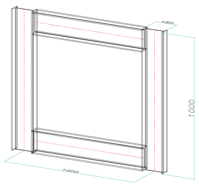
An example will explain how standard beams are fitted.

Proceed as follows:
- Start you steel engineering drawing by selecting Drawing > New.
- Activate the
Steel Engineering tab.
- In the New function group, click the Standard beam
 icon. The Standard
beams function is set as the default and the Beam
selection window is displayed.
- Choose I-beams according to DIN 1025-1,
size 160.
- Click OK
to exit the window.
- The Insertion options menu bar is displayed, and HiCAD asks you to specify the beam start point.
- The first step
is to insert the two perpendicular beams.
- Activate the
Insert beam perpendicular to processing plane
 option
- Activate the
Insert beam via point and length
 option.
- Enter the profile
length, 1000.
- Then, simply
click the mouse to specify the start point of the beam. The beam is fitted
in the specified length.
- In the Insertion options menu bar, enter the rotation angle 90
and click the Rotate
 icon. The 1st beam is rotated.
- Now fit the second
beam, without modifying the insertion options. You want the beam to be generated
in x-distance 1000 from the 1st beam. The start
point of the beam axis is to be used as the reference point
- On the keyboard,
enter R (RELATIVE
point option). Press the left mouse button in order to choose the reference
point. Identify the isolated point at the start of the beam axis (J with the Autopilot). Enter 1000
as the x-distance, 0 for the other
distances.

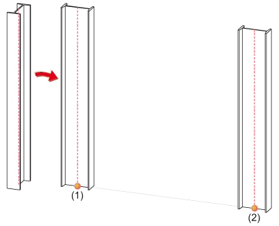
Left:
1st beam - Centre: 1st beam rotated,
(1) Reference point for 2nd beam - Right: 2nd beam directly rotated, (2)
R 100 0 0
The second beam is automatically rotated, as the function
was not exited in between
Click View All  .
This does not end beam fitting
- It is now the
turn of the two other beams to be fitted. The same beam type is to be
used. The Insertion options menu bar is still active
and HiCAD asks you to specify the beam start
point
- Activate the Fit beam in space
 option.
- Activate the
Fit beam via 2 points
 option.

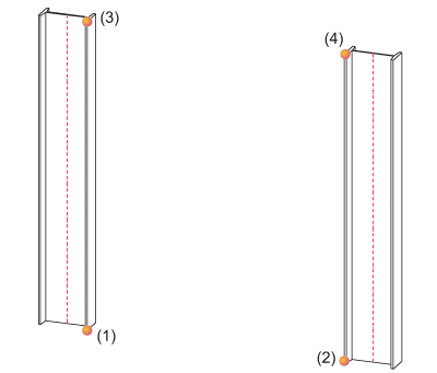
(1)-(2) Start and end points of the 3rd
beam, (3)-(4) Start and end points of the 4th beam
- Specify the start
and end points of the 3rd beam.
- The position
of the 3rd beam is not yet correct, as the centroid was chosen as the
fitting point. Simply choose Bottom right as the
fitting point. The beam is fitted correctly.

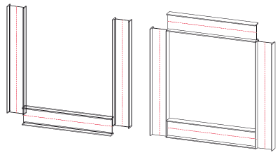
Left:
The position of beam 3 is not yet correct Right:
Position of beam 3 corrected, position of beam (4) is still incorrect
- Do not
change the options, and specify the start and end points of the 4th beam.
The position of the 4th beam is not yet correct. In the insertion options,
simply choose Top right as the fitting point.


Standard Beams
(3-D SE) • Steel Engineering Functions
|
© Copyright 1994-2019, ISD Software und Systeme GmbH
Version 2402 - HiCAD Steel Engineering
Date: 04/11/2019
|
> Feedback on this topic
|


 icon. The Standard
beams function is set as the default and the Beam
selection window is displayed.
 option
 option.
 icon. The 1st beam is rotated.
![]() .
This does not end beam fitting
.
This does not end beam fitting option.
 option.

