
Trim to edge
Trims a beam to a 3-D edge. You can also use 2 points to define the edge.
Trimming to an edge
Left: Original, Centre: Without lengthening, Right: With shortening

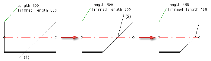
Trim beam, to outer beam edge
Trims a beam to the outer edge of another beam. The beam to be cut must be identified on the section side.
It particularly makes sense to use these functions to trim round beams, pipes etc. and when working with the new design variants.
Beam (1) Trim to beam outer edge (2), Bottom left: Without lengthening, Right: With lengthening

Trim beam, to surface
Trims a beam to a surface. The following options are available for defining the cut surface:
- 2 edges
Identification of two edges. The first edge represents the x-axis and the second the y-axis. - Edge-Point
Identification of an edge as the x-axis near the local origin and specification of a point on the y-axis. - 3 points
Specification of three points. The first point is the origin of the new coordinate system, while the second and third points are points on the x-axis or y-axis. - Surface
Specification of a surface through identification of two edges. - Perpendicular to edge
Specification of a surface through identification of an edge. The surface is then generated perpendicular to this edge.
Trim with lengthening changes the beam length and the trim angle at the identified beam end!

Trim to surface, with lengthening

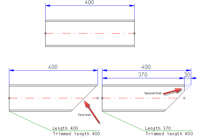
Mitre cut
This function mitre-cuts two beams. The cut can be made flush or with a clearance.
If you enter 0 in the Clearance input field, the beams are mitre-cut flush, i.e. without clearance between the cut surfaces.
If the specified value is greater than 0, a defined gap, a so-called clearance, is created between the cut surfaces. Each of the flush-cut beams is shortened by half of the respective gap width.
Top: Source beams, Bottom: Mitre-cut with clearance (left) and flush (right)
Trim beam, to part
Trims a beam to a different Steel Engineering part, e.g. a pipe. Note that the trim can only be performed if there is a genuine section surface for the parts
Trim with Lengthening adapts the trimmed beam to the part. Trim without Lengthening only trims the part of the beam that abuts the part/intersects it.
Trimming a pipe (1) to a different pipe (2) with lengthening

Trim beam, to 2-D line
Trims a beam to a 2-D line. The cut plane is projected perpendicular to the screen plane. You can also define the 2-D cutting line by specifying two points.
Beam (1) Trim to outer beam edge (2), Bottom left: Without lengthening, Right: With lengthening
 Please note:

