Project: HiCAD Steel Engineering
"Civil Engineering functions" docking window > Steel Engineering > Connections > Front side to web/flange side > Flange > Stabilizing pipe
with a stbilizing pipe.
When connecting the beams it is also possible to mount the stabilizing pipe to plates that already exist on beams.
The created connection consists of
After calling the function, the Stabilizing pipe connection dialogue window will be displayed.
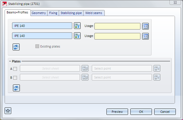
The configuration of the stabilizing pipe connection takes place on the following tabs:
Favourites
The settings of the dialogues can be saved as Favourites and reused at any time. To do this, click on the  icon at the bottom left of the dialogue window to activate the corresponding menu. More information on Favourites management can be found in the Manage Favourites topic of the HiCAD Basics Help.
Buttons
|
Preview |
While the dialogue window is open you can click on the Preview button to display a preview of the connection according to the current settings. You can use the Zoom functions to enlarge or downsize the image. |
|
OK |
Click OK to start the generation of the stabilizing pipe connection. The progress of the generation will be indicated by a progress bar in the status bar. After successful generation of the connection the window will be closed. |
|
Cancel |
Click Cancel to close the dialogue window, without generating the connection. |
![]() Please note:
Please note:

On this tab you specify which beams are to be connected by the stabilizing pipe connection. In the case of the beams, the connection can supply the gusset plates for the connection, or you can also use plates that are already exist on the beam.
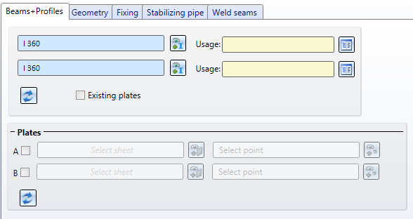
Select - if required, after a click on  - the desired beams. For each of the beams you can choose a Usage from the catalogue. Allowed beam types are:
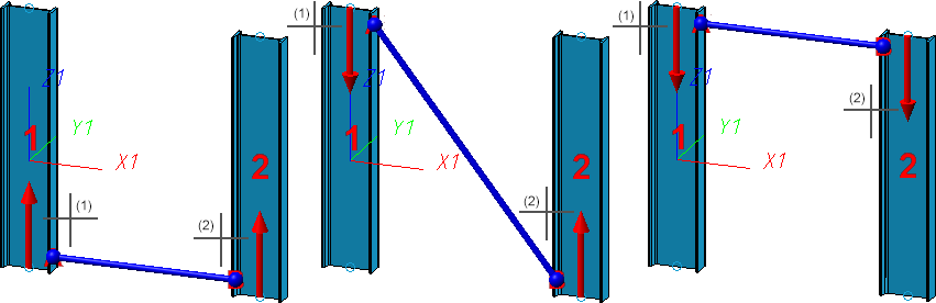
After selecting the beams the position of the stabilizing pipe (depending on the current settings) will be visualized in the drawing. Please note that the selected beam end will affect the position of the stabilizing pipe connection:
Click on the  symbol to restore the settings on this tab to defaults.
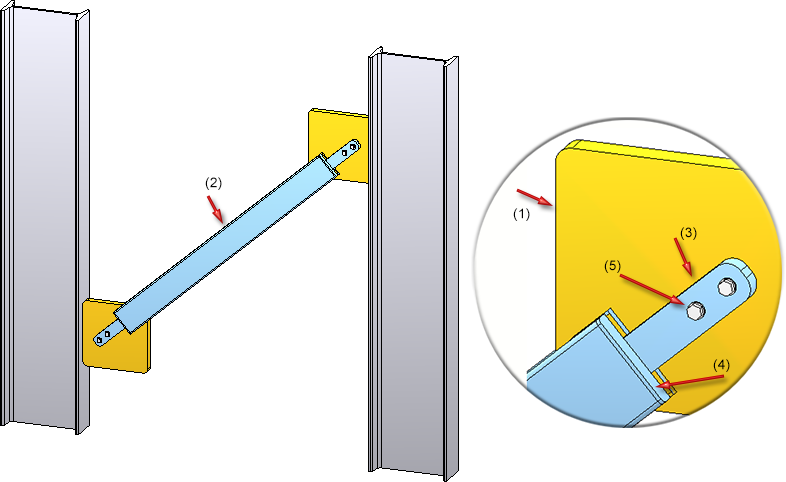
If you want the stabilizing pipe to be mounted to plates that already exist on the beams, you can, in addition to the beams, the desired plates. To do this, activate the corresponding checkbox in the Plates area, choose the plate and specify a point for the centre of the bore grid of the mounting.
Please note the following:
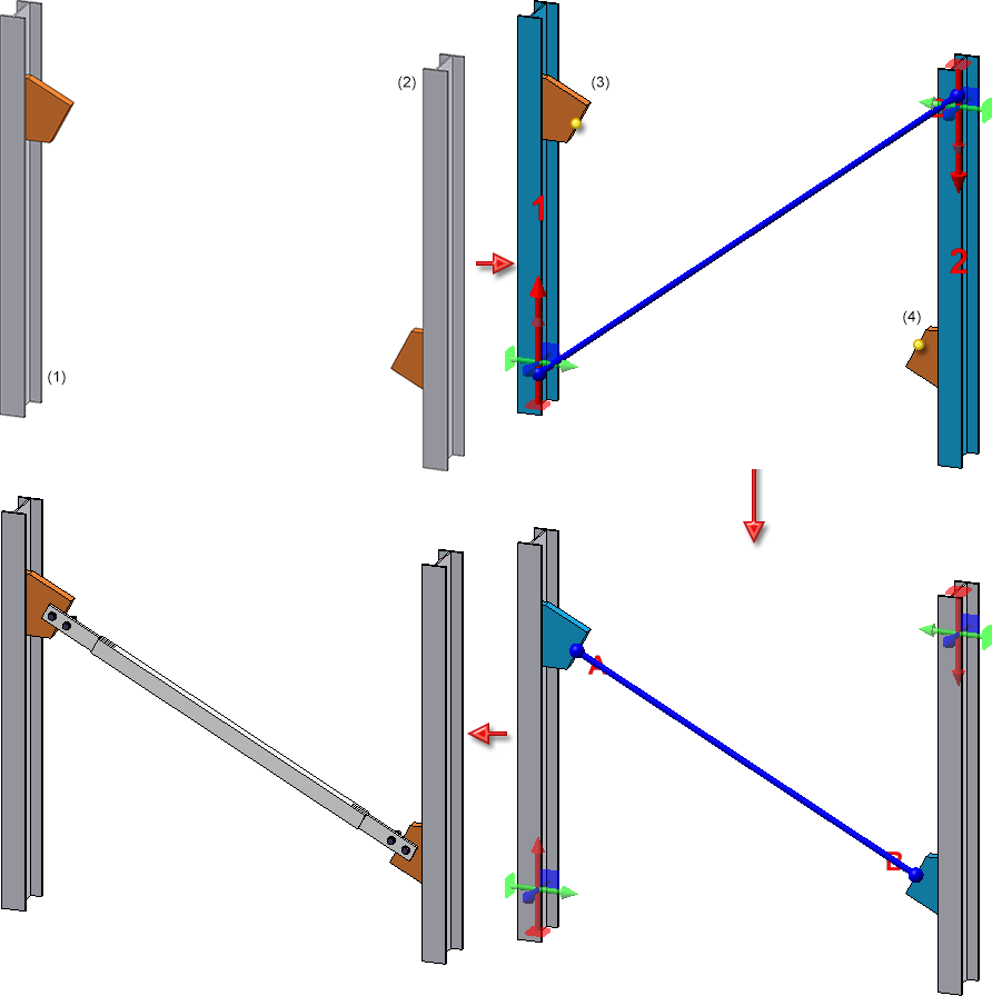
In the image below, the two beams (1) and (2) were identified first. After this, the checkbox A in the Plates area of the dialogue window has been activated. The gusset plate (3) on the first beam was chosen as the plate, and the mid-point of the gusset plate edge was chosen as the point. After this, the same procedure was applied to Plate B (4).
If you want to insert the stabilizing pipe always between plates - independent from beams - activate the Existing plates checkbox. In the Plates area, activate the corresponding checkbox, select the plate and determine a point for the centre of the bore grid of the fixing.
Please note the following:
Here you specify how the stabilizing pipe is to be mounted to the beams. You can do this separately for the mounting to the first beam and the mounting to the second beam using the  and
and  button. If you want to use the same parameters for both mountings, click on the
  button. The settings of the active Pipe-Beam connection will then be applied to the other one.
You can choose between the following two options for insertion of the gusset plates:
|
|
Attaches the gusset plate vertical to the beam. |
|
|
Attaches the gusset plate in the direction of the stabilizing pipe and cuts it to the beam. |
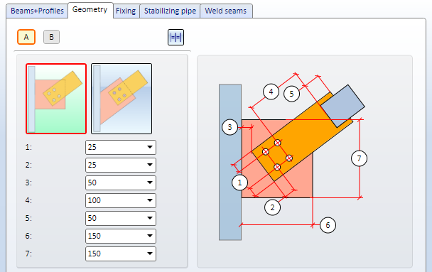
The required dimensions are:
|
(1) |
Distance of bore grid to the right/left edge of the connecting plate (with regard to the centre of the bore) |
|
(2) |
Distance of bore grid to the lower edge of the connecting plate |
|
(3) |
Distance of the connecting sheet to the beam |
|
(4) |
Distance of the bore grid to the stabilizing pipe |
|
(5) |
Distance between connecting plate and stabilizing pipe (not for connections involving T-beams) |
|
(6) |
Width of gusset plate |
|
(7) |
Height of gusset plate |
On this tab you specify how the gusset plate and connecting plates are to be inserted and fixed. You can do this separately for the mounting to the first beam and the mounting to the second beam using the and button. If you want to use the same parameters for both mountings, click on the button. The settings of the active Pipe-Beam connection will then be applied to the other one.
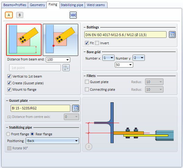
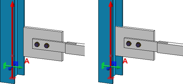
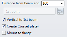
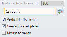
You can choose between the following two options to determine the position of the gusset plate:
|
|
Enter the distance to the beam end.
|
|
|
Determine the distance by a point.
|
By activating the corresponding checkboxes you can determine whether the gusset plate is to be
Left: Mounting to flange; Right: without
|
Other parameters: |
|
|---|---|
|
Gusset plate |
|
|
Boltings |
Here you determine whether gusset and connecting plate are to be bolted together and if so, how. Click on the Furthermore, you have the option to switch the direction of the bolting by activating the Invert checkbox. |
|
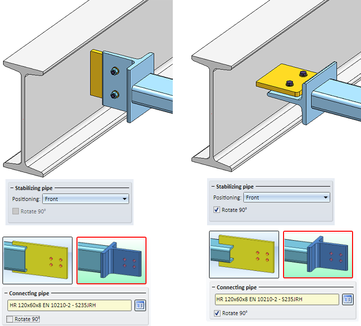
Stabilizing pipe |
Here you can specify whether
Furthermore, you can determine whether the gusset plate is to be mounted to the front or back of the connecting sheet or T-profile, respectively. Also, you can rotate the connecting plate and T-profile 90° by activating the corresponding checkbox.
|
|
Bore grid |
The bore grid determines the arrangement of the boltings on the gusset plate and connecting plate. Enter the number of boltings in X- and Y-direction (max. 2) and the distance between them. If all bores in one direction are to have the same distance, enter the desired distance value in one input field and click on the Equidistant |
|
Fillets |
If you want to fillet gusset plates and connecting plates, activate the corresponding checkbox and enter a fillet radius. |
 Please note that the options for gusset plates are not available if you have chosen to use Existing plates on the Beams+Profiles tab.
On this tab you specify the parameters for the connecting pipe and the connecting plate. Instead on a connecting plate reaching "into the pipe" you can also use a small T-beam that will be mounted to the end of the stabilizing pipe. Choose a connecting pipe and a connecting plate.
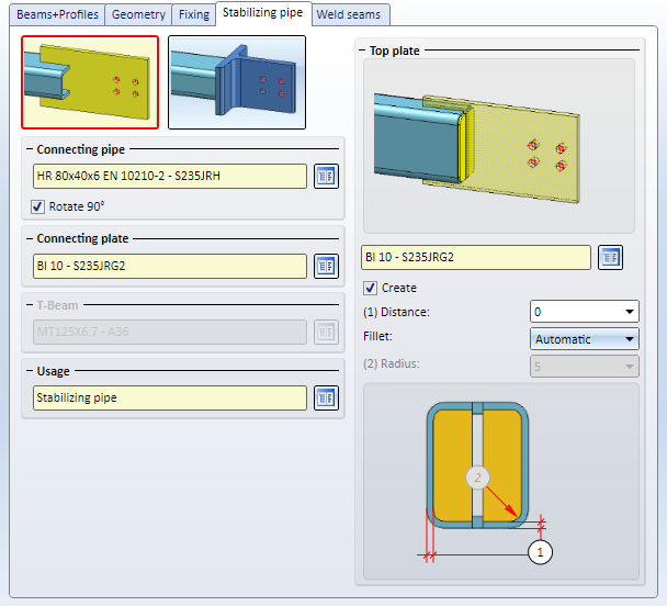
Choose the desired procedure - Connecting plate or T-beam - and choose the desired connecting pipe from the catalogue. If you want to rotate the connection 90 degrees, activate the corresponding checkbox.
|
|
Connecting plate Choose the desired connecting plate from the catalogue. If you want to attach a Top plate to the end of the connecting pipe, activate the Create checkbox and enter the distance (1) of the top plate to the edge of the connecting pipe (5). Choose the option for the filleting of the plate from the listbox:
|
|
|
T-beam Choose the desired T-beam from the catalogue. |
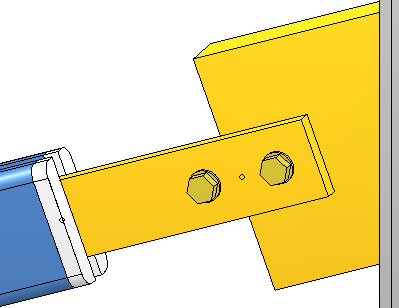
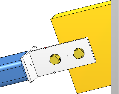
Left: Top plate on connecting pipe; Right: T-beam
A Usage for the pipe can be chosen from the listbox. The default setting is Stabilizing pipe.
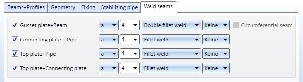
On this tab you determine which weld seams are to be created.
Specify where you want to create weld seams by activating the corresponding checkboxes. For each edge you can choose the type of thickness designation, the weld seam thickness, the weld seam type and the inspection category. If you require a Circumferential seam, activate the same-named checkbox.

Connections + Variants (3-D SE) • Dialogue Window for Connections - Type I (3-D SE) • The Catalogue System for Connections + Variants (3-D SE)
|
© Copyright 1994-2019, ISD Software und Systeme GmbH |


 symbol and choose the required part from the standard parts catalogue.