Project: HiCAD Steel Engineering
Gusset Plates
"Civil Engineering" docking window > Steel Engineering > Macros > Gusset plate
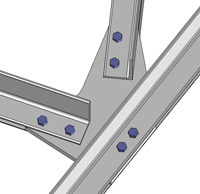
The Gusset plate function enables you
to insert and bolt plates by specifying the main beam (main beams) and the
diagonals or posts to be shortened.
Basic procedure:
- Activate the
Gusset plate function.
- Activate the
Material tab and make the
necessary entries.
- Switch to the
Gusset plates tab. Choose
the desired options and enter the required data.
- Choose OK to exit the tab.
- Next, HiCAD asks
you to identify the main direction. Use the right mouse button to end
the identification
- Next, identify
the beams to be shortened.
The following figures provide an overview of the possible uses of gusset
and batten plates.
Prerequisite for the calculation:
- The axes of all connections
projected onto the plate plane intersect in one point - midpoint -, which
lies on the projected axis of the traversing beams.
- The shortening dimensions
and the bolt offsets give rise to the plate contour edges. Intermediate
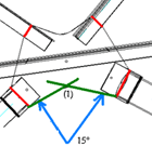
edges are created and clipped at an angle of at least 15°, the so-called
edge angle, at these contour edges. If this cut produces an acute external
angle <
90°, the plate is cut straight between these connections; otherwise, the
two edges are taken as contour edges.
|

Edge angle (1)
|
Terms
- Main
direction
The main direction describes the beam or the beams to which a gusset
plate is fitted. HiCAD automatically identifies whether the gusset plate
is fitted between two beams or whether it is added to a beam such as a
double T-girder.
If the beam is not bolted in the main direction, the bolting
must not be set in the main direction in the Material tab before the flange
plate is fitted!
- Posts
and Diagonals
The distinction between posts and diagonals enables you to use
a special bolting to set connections perpendicular and skew to
the main direction.
 Note:
Note:
- The midpoint of the
plate is used as the midpoint for the bolting of the main beams!
- Gusset plates can
also be connected to pipes or HEB girders. In this case, to determine
the main direction, you identify the beam and then press the right mouse
button. Next, you specify the diagonals and posts.

Settings on the 'Material' tab
- Plate material
Choose the desired material from the list box.
- For:
Choose the fitting direction. If the beam is not bolted in the main
direction, the bolting must not be set in the main direction in
the Material tab before the gusset plate is fitted!
- Bolt
type
Select the bolt type. The template which you assigned to this type
via the New
bolting function is used for the bolt connection.
- Strength
class and Diameter
Choose the bolt diameter and the strength class from the corresponding
list box here.
- Bolting Offset
The offsets of the boltings can either be copied from a table
or entered directly into the fields, with e1 being the distance to the edge in force direction to the first
bore for the bolting and e2 the corresponding offset perpendicular
to the force direction. p1 is the hole offset in force direction/skew
to the force direction, p2 the hole offset perpendicular to the force direction.
The values that you enter on this tab are the default
settings the next time you call the function!

Settings on the 'Gusset plate' tab
- Edge
Angle
This value determines the angle at which the intermediate edges for
the calculation are placed on the contour edges. The angle must be at
least 15°.
- Fillet
Here, you activate the relevant options to define whether you want
the plate to be filleted. If yes, enter the fillet radius, in addition.
- Main
direction
Enter the required data for the main direction here.
- Values w1, w2 and
w3 are determined via the beam and define the distance of the bolting to the edge of the beam. In the case of equilateral beams, values w1 and
w3 are identical. The values can either be taken from the standard table
or entered directly. Standard table here refers to the table defined for
the beam in the standard catalogue. You can use the catalogue editor to
define new catalogues and tables.
If you use series beams, i.e. derive the beams from 2-D parts, you
can also assign parameters w1, w2, w3 to the 2-D figures. In this case,
the values assigned to the 2-D part are used for fitting batten or gusset
plates. The Detect from table checkbox
needs to be active in this case.
- If you do not want
any bolts to be fitted in main direction, deactivate the Bolts
Yes/No option. Bolts can also be arranged with
an offset

3 rows, 5 columns, left: without offset,
right: with offset
- Shortening
Specify the shortening offset for the
diagonals and posts here. This is the value by which the beam is
shortened when the plate is fitted.
- Beams
to be shortened
You define the data for the diagonals and posts here. To do this,
select the relevant connection from the list box and enter the data for
this connection. The same input fields as for the main direction are available.
- Plate:
Trim plane
If you want the gusset plate to be trimmed, activate the checkbox.
HiCAD then asks you to specify the trim plane before finally fitting the
plate.


Further Connections + Construction Aids
(3-D SE) • Connections + Variants (3-D
SE) • Steel Engineering Functions
|
© Copyright 1994-2019, ISD Software und Systeme GmbH
Version 2402 - HiCAD Steel Engineering
Date: 04/11/2019
|
> Feedback on this topic
|

![]() Note:
Note:
