> Default settings and click the Favourites
  icon at the bottom left of the to specify whether Bystronic- or LVD-specific annotations are to be output.
 Project: HiCAD Interfaces
The interface between Bystronic (BySoft Programmer) or LVD and HiCAD allows the export of bending data, providing the required "DXF Extended Entity Data" by means of a so-called CyCAD DXF file.
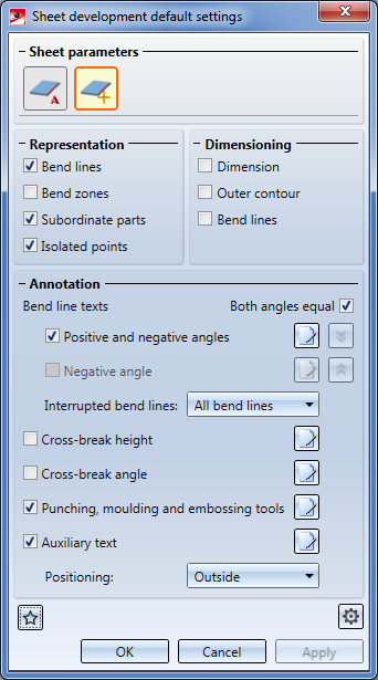
Open the Sheet Metal Ribbon tab and select Sheet development > Update > Default settings and click the Favourites icon at the bottom left of the to specify whether Bystronic- or LVD-specific annotations are to be output.
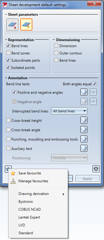
Your selection in the pull-down menu sets the default settings in the dialogue to the specific values for Bystronic or LVD, respectively.
The Auxiliary text can be modified subsequently in the drawing if required.
You can also activate the machine-specific texts for drawing derivations. To do this, open the Drawing tab, choose Itemisation/Detailing > Derive... and, in the dialogue window, click the Sheet developments button. In the Sheet development parameters dialogue window you can then proceed as described above: Click the Favourites icon at the bottom left and choose either LVD or Bystronic.
 Please note:
For LVD export, the following parameters should have been set:
For DXF export with bending data you also need to add some specifications in the hcadacad.dat file. HiCAD creates outer contours and bend lines in different colours. For the export you need to specify that the HiCAD colours are to be assigned to the corresponding DXF layer. Bend lines and their texts must be located on the BENDS layer , everything else on the OUTLINE layer (in the excerpt below, the corresponding lines are highlighted in bold type).
ACDXF 2000 # 12 or 2000 (default=2000)
ACDWG 0 # Version of DWG file (9,10,12,13,14,2000,2004,2007,2010)
DWGWAIT 0 # 1 = HiCAD waits until DWG file is saved
BEMAS 0 # Create geometric/real dimension (0/1) Geometrische/echte Bemassung erzeugen (0/1)
HATCH 1 # Create hatch: 0=hatch blocks 1=HATCH contours Schraffurerzeugung: 0=Schraffur-Bloecke 1=HATCH-Konturen
SPLINE 1 # Create AutoCad B-Splines
TPOINT 1 # Retain text reference points Text-Bezugspunkte beibehalten
CPAGE 0 # ANSI-Codepage-number (0=Default=1252) ANSI-Codepage-Nummer (0=Default=1252)
DIR # Entry for path Eintrag fuer Pfad
ZVD 0 # Database (0/1) Datenbank (0/1)
FIGBL 0 # Figure block transfer (-1/0/1) Figur-Block Uebertragung (-1/0/1)
FIGB1 1 # Figure entities transfer, if 1 block (-1/0/1) Figur-Entities Uebertragung, wenn 1 Block (-1/0/1)
FIGLA 0 # 0 , 1=all FIGs as layer , -1=individual FIGs 0 , 1=alle FIGs als Layer , -1=einzelne FIGs
LPOLY 1 # Create POLYLINES (0/1) POLYLINES erzeugen (0/1)
NKST 8 # Number of decimal places (max.=14) Anzahl der Nachkommastellen (max.=14)
NOKOM 0 # Suppress comments (0/1) Kommentare unterdruecken (0/1)
NOVER 0 # Suppress DXF version number (0/1) DXF-Versionsnummer unterdruecken (0/1)
AUNIT -1 # Value for Header variable $AUNITS (-1=omit) Wert fuer Header-Variable $AUNITS (-1=weglassen)
VISRE -1 # Value for Header variable $VISRETAIN (-1=omit) Wert fuer Header-Variable $VISRETAIN (-1=weglassen)
ZEROPT 1 # Move figure to zero point (0/1=geometrie/2=all) Figur auf den Ursprung verschieben (0/1=geometrie/2=all)
#LTDEF -1 # Use HCADACAD_LTDEF.DAT for LTYPE-Table HCADACAD_LTDEF.DAT fuer LTYPE-Table verwenden
LTDEF 1 CONTINUOUS Solid line
LTDEF 2 DOT ..............
LTDEF 3 HIDDEN -- -- -- -- --
LTDEF 4 DASHDOT --.--.--.--.--
LTDEF 5 STRICHPUNKT2 --.--.--.--.--
LTDEF 6 STRICHPUNKT3 --.--.--.--.--
LTDEF 7 PHANTOM --..--..--..--
LTDEF 8 PHANTOM2 --..--..--..--
LTDEF 9 PHANTOM3 --..--..--..--
LTDEF 10 STR3PKT --...--...--...
LTDEF 11 2STRPKT --.--.--.--.--
LTDEF 12 GESTRICHELT2 -- -- -- -- --
LTDEF 13 2STR2PKT --..--..--..--
LTDEF 14 STR3PKT2 --...--...--...
LTDEF 15 2STR3PKT --...--...--...
LTDEF 16 STRKSTR -- - -- - -- -
LTDEF 17 STRKSTR2 -- - -- - -- -
LTDEF 18 STRKSTR3 -- - -- - -- -
LTDEF 19 PUNKT2 ..............
#
BYLAY 7 CONTINUOUS * # Entry of all HiCAD layer names
BYLAY 3 CONTINUOUS LE_GREEN # BYLAY: Default colour, default line type, layer name
BYLAY 1 CONTINUOUS LE_RED # BYLAY: Default colour, default line type, layer name
BYLAY 7 CONTINUOUS 50 LE_ALL # BYLAY: Default colour, default line type, lineweight, layer name
BYLAY 3 HIDDEN LE_HIDDEN1
BYLAY 7 CONTINUOUS LE_HIDDEN
BYLAY 7 CONTINUOUS LE_MIDDLE
BYLAY 2 CONTINUOUS TXT_YELLOW
BYLAY 2 CONTINUOUS TXT_DIM49
BYLAY 7 CONTINUOUS TXT_ALL
BYLAY 4 CONTINUOUS DIM49
BYLAY 3 CONTINUOUS HATCH
BYLAY 4 CONTINUOUS BENDS
BYLAY 0 CONTINUOUS OUTLINE
#
# ==========================================================================
# Layer-Zuordnung (lay=9999=all // col=999=all // width=0=all // type=0=all)
# ==========================================================================
# lay col w typ ACAD-layer-name
# ------------------------------
LAYER 9999 004 0 00 BENDS
LAYER 9999 999 0 01 OUTLINE
#
#LAYER 0001001001 LE_GREEN # (Format ohne Blanks ist auch noch gueltig)
#
#LAYER * # Take over all LAYERS with name which exist in the ZTL
#
TXTLA 9999 004 BENDS # LAYER: 1-4=layer 5-7=colour, layer name
TXTLA 9999 999 OUTLINE
TXTLA 0049 005 TXT_DIM49
TXTLA 9999 999 TXT_ALL
SONST 0049 DIM49 # Otherwise: Layer, layer name
SONST 0001 HATCH #
SONST * # Take over all LAYERS with name which exist in the ZTL
#
# ==========================================================================
#
FNTBR 1 # Width adjustment for proportional text fonts
FNTST 1 # Style concerning text types (0) - fonts (1)
STYLE 1 MONOTXT monotxt.shx # STYLE: No., text style, font file
STYLE 2 STANDARD 1.0 # STYLE: No., text style, width correction
STYLE T1 ARIAL arial.ttf 1.0 # STYLE: No., text style, font file, width correction
STYLE T3 "ARIAL Narrow" ArialN.ttf 0.95 # STYLE: No., text style, font file, width correction
# Special character conversion ASCII->ANSI: omitted for DXF HiCadWindows->ACadWindows
#ASCII 228 132 ae
#ASCII 246 148 oe
#ASCII 252 129 ue
#ASCII 196 142 AE
#ASCII 214 153 OE
#ASCII 220 154 UE
#ASCII 223 225 sz
#ASCII 176 248 degree
#ASCII 248 155 diameter
#ASCII 177 241 +/-
#
COLVD 1 # HiCAD colour for overlap lines HiCAD-Farbe fuer Verdeckungslinien
#
COLOR 0 7
COLOR 1 3
COLOR 2 5
COLOR 3 4
COLOR 4 1
COLOR 5 0
COLOR 5 2
COLOR 6 6
#COLOR 7 8 # Default: COLOR(dxf)=COLOR(HiCAD)+1
The parameters FIGB1 (Figure entities transfer) and FIGBL (Figure block transfer) should be set to 0 for the LVD export.
The parameter TPOINT (# Retain text reference points/ Text-Bezugspunkte beibehalten) should be set to 1, to retain the alignment (for Bystronic: "Centred") of the bend line texts in the blank for the export to the DXF format. Centred bend line texts will then retain their insertion point on the bend line mid point. If the parameter is missing, or if the value is not 1, the texts will be aligned left for DXF export. This may result in failed text assignments if a displaced insertion point is located outside the edge.
The lines beginning with STYLE determine the settings for the font. For example, if Arial is to be used as default font, it can be set as "STANDARD" for the export. The existing entries are to be changed or commented out accordingly.
(...)
#STYLE T1 ARIAL arial.ttf 1.0 # STYLE: No., text style, font file, width correction
#STYLE T3 "ARIAL Narrow" ArialN.ttf 0.95 # STYLE: No., text style, font file, width correction
STYLE T1 ARIAL STANDARD 1.0 # STYLE: No., text style, font file, width correction
STYLE T3 "ARIAL Narrow" STANDARD 1.0 # STYLE: No., text style, font file, width correction
(...)
If COLOR 5 0 has been set, bend line texts will be output in yellow by default. If you want them to be output in a different colour, change the value accordingly.
For the import of a DXF file in HiCAD (e.g. for the checking of the result), one more line should be adjusted in the acadhacad.dat file:
ACDXF 2007 # Use AutoCad interface format xxxx
BEMAS 0 # Create geometric/real dimension (0/1) - Geometrische/echte Bemassung erzeugen (0/1)
LAYFI 0 # Assign block figure/layer figure (0/1) - Block-Figur/Layer-Figur Uebertragung (0/1)
LAYNA 1 # Transfer dxf-layer name as HiCAD-layer name (0/1) - Layernamen als Schichtnamen uebergeben (0/1)
LAYNR 1 # Transfer numerical dxf-layer name as HiCAD-layer number (1/0) - Numerische Layernamen als Schichtnr.uebe
(...)
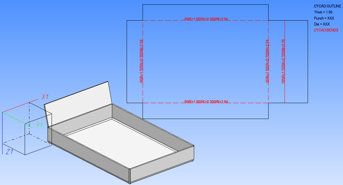
After having prepared all files correspondingly, the CyCAD data will be included into your sheet developments (Sheet Metal > Sheet development > Develop sheet (3-D SM)).
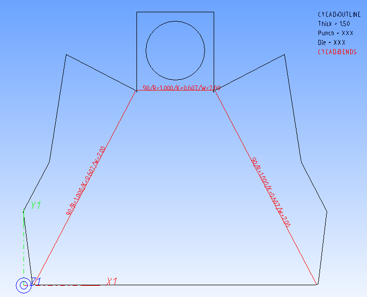
The information given for each bent edge (red) consists in the bend angle (in the above example 90 degrees for each edge), the radius (R=...), the allowance of the K-factor (K0...), and the lengthening (W=...). Continuous lines next to the information indicate upward bendings, dashed lines indicate downward bendings. These are the bending data of the CyCAD "BENDS" layer.
The OUTLINE layer contains the information on the outer contour. THICK indicates the thickness of the sheet edges, PUNCH and DIE refer to the upper and the lower tool which can, if they are known, indicated manually in the text.
To export the file in CyCAD DXF format, select Sheet Metal > Sheet development > Extras >
  DXF - Complete . If you want to export the file in LVD format, select Sheet Metal > Sheet development > Extras > LVD - 2-D data
  (written will be one DXF and one .CBBatchInput file.


|
© Copyright 1994-2019, ISD Software und Systeme GmbH |