Project: HiCAD Interfaces
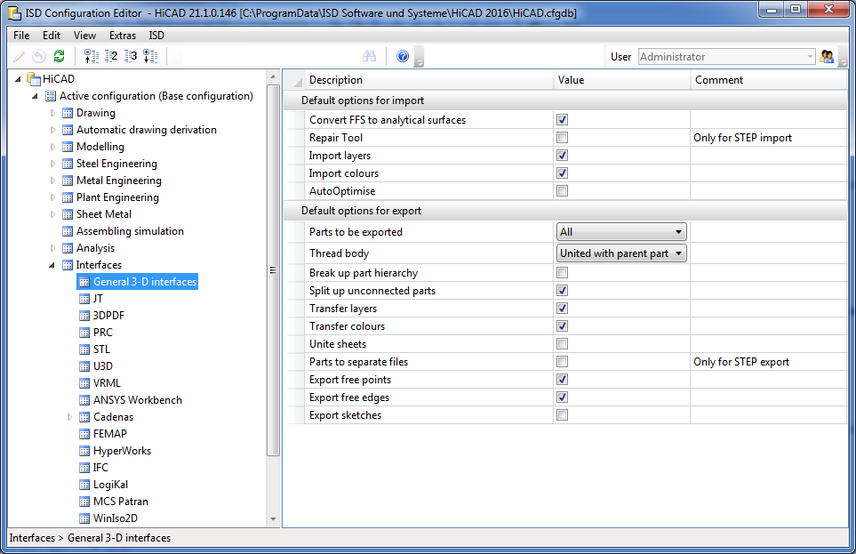
In the ISD Configuration Management under Interfaces, you can define which default settings are to apply to the import and export of the general 3-D interfaces such as Step, IGES, DXF/DWG, etc. These settings are then displayed as default in the respective import/export dialogue when called up in HiCAD.
In the import/export function dialogues, via the symbol  Apply parameters from Configuration Editor, the default specified in the Configuration Editor can be set at any time.
|
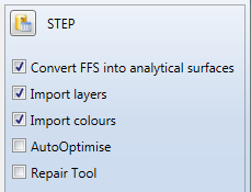
Convert FFS into analytical surfaces |
Determines whether FFS are to be converted into analytical surfaces. Deactivating this option may be useful for sheets. |
|
Repair Tool |
If problems occur when reading "bad" STEP files, a Repair Tool with extended correction and repair functions is available, which is separately licensed. Activate the checkbox if this tool should be used. (The Defaultsystem file is located in the directory of the HiCAD installation under ...\sys\CADfix\Default\Import\ and is called STEPRepair.cwc) |
|
Import layers |
These options refer exclusively to the properties of the entire part. |
|
Import colours |
|
|
AutoOptimise |
If this checkbox is ticked, a union of (divided) edges and surfaces is carried out directly during the import (corresponds to the HiCAD function 3D-Standard > Tools > Surface > Further ... > Optimise part). |
|
Take texts from model |
Activate this option to transfer the annotations of the AutoCAD model to HiCAD dimensioning. The texts will be imported as part annotations with leader line. Before the import, their appearance can be influenced via the Annotation settings(3-D Dimensioning + Text > Leader > Settings - Change ) in the system file ...\sys\DXF_Importtext.ftd. |
|
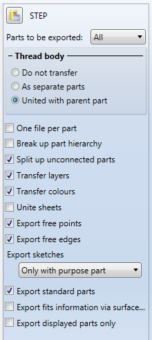
Parts to be exported |
Here, you determine whether the entire drawing or only the active part or parts list is to be exported. |
|
Thread body |
Thread bodies can be exported either as individual parts or as a union with the parent body. If you do not want threaded bodies to be exported, select Do not transfer. |
|
Break up part hierachy |
If you do not want to transfer the existing hierarchy of the parts during their export, activate this option. When the part structure of the drawing is broken up, all solid parts will be merged into one part. |
|
Split up unconnected parts |
The hierarchy of the parts in a drawing, without their geometrical relations to each other, will be broken up if you deactivate this option. Several solids which are, according to HiCAD part structure, one part, (e.g. Extruded parts with several closed contours) will then be broken up into individual parts. If this option is active, the parameter Break up part hierachy (at least when reloading in HiCAD) has no effect, since the parts that have been resolved to one part are made into individual parts again by the disassembly. If you intend to Break up part hierachy, the option Split up unconnected parts should be deactivated. |
|
Transfer layers Transfer colours |
Activate these checkboxes if layers and colors should also be taken into account during export. |
|
Unite sheets |
Activate this option if you want to unite all sub-parts of a sheet with its super-ordinate part, thus forming one part. |
|
Parts in separate files |
If this option is activated, then not the entire drawing is saved in one file, but each individual part in a separate file. |
|
Export free points |
Activate or deactivate these checkboxes to allow or suppress the export of free points and/or free edges in the drawing (suppress their export if they may cause any problems). |
|
Export free edges |
|
|
Export sketches |
Activate this checkbox if you want sketches to be exported as well. When you activate this checkbox, please also activate Export free points and Export free edges; otherwise, the sketch may not be exported completely. |
|
Export standard parts |
Here you specify whether standard parts (bolts, roller bearings, springs ...) are to be considered for export. |
|
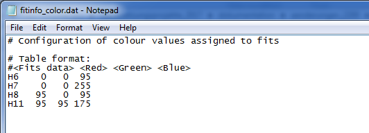
Export fits information via surface colour |
Here you can specify by activating or deactivating the checkbox whether fits information are to be transferred via the surface colour. On the exported STEP part the diameter of the corresponding bore will be highlighted. For this, the option Transfer colours must be active. In the sys directory of your HiCAD installation you will find the configuration file fitinfo_color.dat, where the assigning of RGB colour values to fits data is specified. |
|
Export displayed parts only |
Only the parts that are visible in the active HiCAD view will be exported. |
![]() Please note:
Please note:
Powder marking lines are exported automatically. If this is not desired, the export can be prevented by setting the ExportPowderMarkingLinekey to 0 in the Windows registry under the path HKEY_CURRENT_USER\SOFTWARE\ISD Software und Systeme\HiCAD nnnn\DataExchange (nnnn stands for the HiCAD version, e.g. 2019).
Apart from General 3-D interfaces you can find the parameters for the default settings for the following interfaces:

|
© Copyright 1994-2019, ISD Software und Systeme GmbH |