
Project: HiCAD P+ID
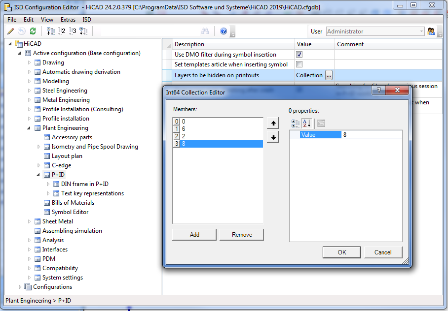
You have now the option to specify layer-specific printing settings in the P+ID module via the Configuration Editor (at Plant Engineering > P+ID). For this purpose you can define a list with layers that are to be excluded for printouts. Click the Add button to expand the list. Beneath Properties you can then enter the number of the layer.
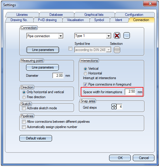
You have now the option to define the space widths of connection interruptions. For this purpose you can find an editing box on the Connections tab of the P+ID Settings dialogue window, where you can enter the desired space width for interruptions in mm.
The procedure for creating new pipelines has been changed as follows:
Automatically assign pipeline numbers
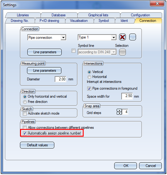
First, open the Connection tab of the P+ID Settings dialogue window and activate the  Automatically assign pipeline number checkbox.
Then, you need to specify various settings in the symbol mask for the pipeline symbol, as the related entry for the attribute Pipeline number plays a decisive role for the generation. The entry %COUNT(1:0:RL) , for example, ensures that natural numbers beginning with 1 will be used as pipeline numbers. The entry %PIDAT(430)%PREPOST(%PIDAT(431):-)%PREPOST(%PIDAT(432):-) for the Code ensures that codes in P+ID are generated in the way would expect it.
Further useful information about generation instructions can be found in the topic Take Over Database Attributes as Dialogue Text.
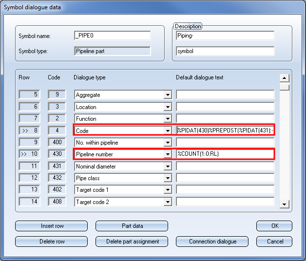
The mask as shown in the image above is the default mask in the P+ID libraries ISDDINSYM1_GER and ISDDINSYM1_ENG, respectively.
You can now choose whether you want to exchange P+ID symbols via a reference symbol (as in previous versions) or determine a matching symbol via the symbol selection dialogue (new).
The context menu of symbols (right-click) now looks as follows:
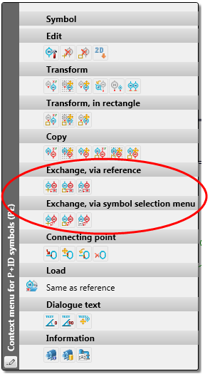
On the toolbar the following editing options are now available:
|
|
If the exchange is valid, the selected symbol is replaced. |
|
|
|
This option enables you to draw a rectangular box by specifying two points with the cross-hairs. All symbols within this box matching the selected symbol are replaced. HiCAD then highlights these symbols. If required, the highlighting can be retained until the next time the screen content is redrawn. |
|
|
|
This option exchanges all symbols on the current drawing sheet that match the currently selected symbol. HiCAD tells you how many symbols have been replaced and then highlights them. If required, the highlighting can be retained until the next time the screen content is redrawn. |
You can now even edit a pipeline symbol that does not exist on the current drawing sheet, but to which pipeline parts or pipeline info symbols have been subordinated on the current sheet. To do this, edit the subordinated parts. To do this, activate the Edit pipeline symbol ![]() function on the P+ID Ribbon tab and choose a symbol that has been subordinated to the pipeline symbol.
function on the P+ID Ribbon tab and choose a symbol that has been subordinated to the pipeline symbol.
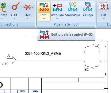
Then, choose a symbol that is subordinated to the pipeline symbol.
The Edit symbol mask will then be displayed for the pipeline symbol.
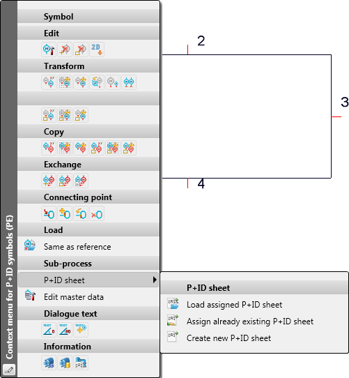
HiCAD P+ID R+I now supports so-called block symbols. These are symbols that represent a P+ID sheet.
In the ISD library ISD_PROCESSFLOW.SZA such a block symbol is already available. Users can create such symbols using the Symbol type 18 = Schema block. After inserting a block symbol, you can call the editing functions for the block symbol with a right-click on the symbol.
|
|
Load assigned P+ID sheet |
If a P+ID sheet has been assigned to a block symbol, you can open the assigned sheet via the context menu of the symbol. |
|
|
Assign already existing P+ID sheet |
Use this function to open a dialogue window with a list of already existing, selectable P+ID sheets that have not been assigned to a a block symbol yet. If no P+ID sheets are available for selection, a corresponding message will be displayed. |
|
|
Create new P+ID sheet |
This function opens the known master data dialogue window when creating a new sheet. |
|
|
Edit master data |
Use this function to edit the master data of the assigned P+ID. |
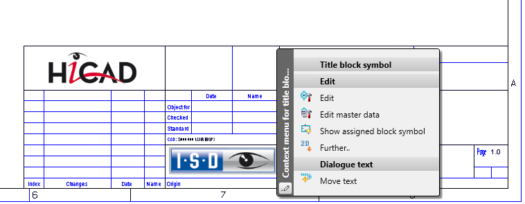
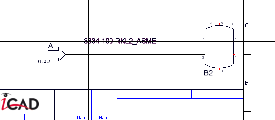
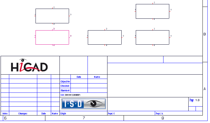
When you right-click on the title block of a sheet and choose Show assigned block symbol  , the corresponding P+ID sheet containing the block symbol will be loaded, and the block symbol will be highlighted:
P+ID dialogue types can be assigned to user-defined attributes can be assigned to on the p+ID attribute assignment tab of the Plant Engineering Settings dialogue window that you open by choosing P+ID > Settings  .
.
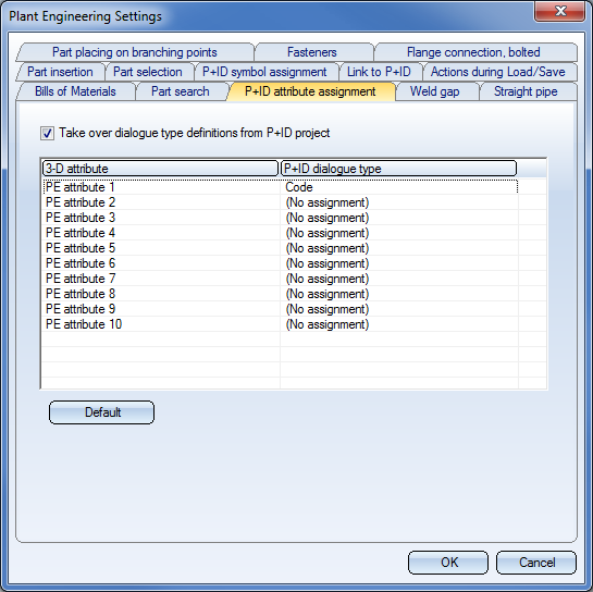
When you change one of the assigned dialogue types for a symbol in a P+ID, and then switch to the 3-D layout plan via P+ID > Link to 3-D > Assigned 3-D layout plan  , the new value of the dialogue field will be applied to the attributes of the part.
Example: Let us assume that you choose the dialogue type Code for the Plant Engineering attribute 1 and, in the P+ID, change the Code for a Vessel symbol from B1 to B2. When switching to the 3-D layout plan, the PE attribute 1 will be changed for the affected Vessel from B1 to B2. This will also be confirmed by a corresponding info message.

|
© Copyright 1994-2019, ISD Software und Systeme GmbH |


