
Project: HiCAD Profile Installation
Profile Installation > New/Change > Profile installation
Profile Installation > New/Change > Define transverse joint edges 
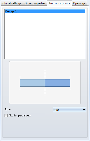
The Transverse joints tab allows you to configure the processing of transverse joints in profile installations. In this way you can choose whether transverse joints are to be cut or not.

You can use individual graphical elements within the profile installation sketch for the creation of transverse joints. You mark these elements with the Define transverse joints function.
To mark the edges, call the Define transverse joints function on the Profile Installation Ribbon. Then click on the graphical elements in the sketch that you want to use. These elements will be highlighted in red in your drawing. To remove the marking of an element, click this element again. Press the MMB to exit the function.
This tab of the dialogue window is divided into 2 areas: In the upper area of the window you find a list of all marked edges in the sketch. When you select an edge here, you can specify further settings in the lower area of the window. The chosen edge in the sketch will be indicated.
You can also choose multiple edges. Hold down the CTRL key while selecting several edges one by one, or the SHIFT key to select a complete set of edges.
In the lower part of the window you can choose the type of the joint and specify the corresponding settings.
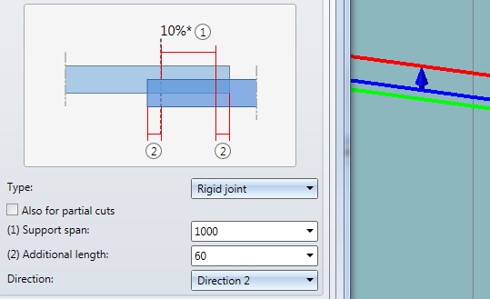
For every type of joint except for Do not cut the Also for partial cuts option is available. This option determines whether a cut on a profile should even be applied if this cut does not run through the entire profile, but only through part of it. An example of this would be profiles that are to be cut diagonally but not through their entire width.
The effect of this option is that the selected polyline(s) have no influence on the active plane.
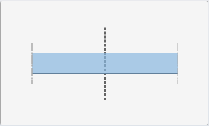
The profiles of the active plane are cut to this line.
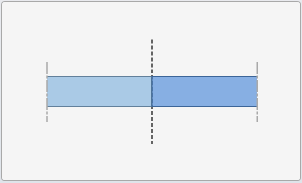
The profiles are cut to this line; however, an overlap to both sides of the edge remains. You can specify both lengths for the overlaps separately, or activate the Both equal checkbox to automatically apply the same value for both lengths.
The profiles are cut with shortenings, creating a clearance in this way. You can specify the values for the clearances separately, or activate the Both equal checkbox to automatically apply the same values for both.
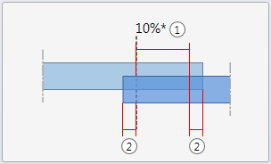
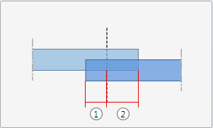
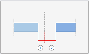
For one of the two profiles a projecting Support span (1) is left to stabilize the joint. In addition, you have the option to apply an Additional length (2) to both sides.
You can specify via the Direction selection field which of the two profiles is to be the projecting profile. In the model drawing the selected setting will be visualized: An arrow shows the chosen direction, while a red line represents the cutting of the profile against the arrow direction, and a green line the cutting of the profile in arrow direction.

|
© Copyright 1994-2019, ISD Software und Systeme GmbH |