Project: HiCAD Parametrics
HCM 3-D is a parametric technology which you can use, for example, to implement movement analyses and function simulations.
To enable you to do this, individual parts are grouped into complex assemblies (Assembly Modelling) by assigning so-called constraints, i.e. by means of
HCM 3D then transforms the relevant parts, thereby enabling the defined constraints to be fulfilled.
The following should be borne in mind: constraints are assigned to individual geometry elements of assemblies. These geometry elements include
However, it is not only these elements, but the entire assembly that is transformed. The HCM models are not calculated immediately upon loading a construction, but only when an HCM model is accessed.
You may also activate the Part HCM Selection context menu with a right click to select the reference geometries. The context menu offers the following options:
| Part HCM Options | |
|
Geometry |
Selection by identification of the required geometry |
|
Surface |
Selection of a surface via identification of 2 edges. |
|
X-, Y- or Z-Axis |
Selection of the X-, Y- or Z-axis. |
|
XY-, XZ- or YZ-Plane |
Selection of the XY-, XZ or YZ-plane |
|
Cancel |
Cancels the menu. |
![]() Please note:
Please note:
In addition to the assignment of constraints and the associated position of the parts, the Dragger is one of the most important components of HCM 3-D. It allows you to use the mouse to move individual parts or to perform an automatic motion simulation, while complying with already assigned constraints. This enables you to perform dynamic manipulations even on complex models, i.e. spatial movements are controllable and are visualised in real time. This means that it is also easy for you to implement three-dimensional kinematic analyses.

When assigning constraints, the part structure and hence the arrangement of the parts is crucial.
You can assign constraints only within a main assembly and only to parts of an active body.
If, for example, you activate a main part with sub-parts, HiCAD regards the sub-parts of a hierarchy as one unit. No constraints can be assigned within this unit.
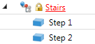
In the 3-D part structure, part containing dimensional or positional constraints are indicated by a black H against yellow background:
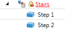
In the Configuration Editor at System settings > Assembly HCM you find the setting option Show HCM errors in part structure?. This function is deactivated by default. If you activate this option, inconsistent HCM models in assemblies will be marked in the 3-D structure with a corresponding symbol.
In this case a red H will be shown instead of a black H. This marking will also be applied to superordinate parts and assemblies to indicate the inconsistencies up to the top level of the affected element:
 Please note:

|
© Copyright 1994-2019, ISD Software und Systeme GmbH |