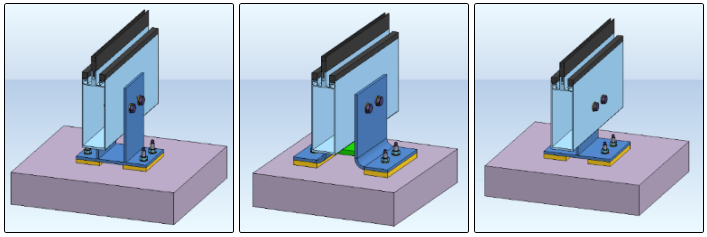
From left to right: Fixing brackets 1410, 1420, 1430.
Project: HiCAD Metal Engineering
"Civil Engineering functions" docking window > Metal Engineering/Facade Engineering> 3-D Metal Engineering > Metal Engineering beam/profile connections > Fixing bracket
In the Civil Engineering functions docking window (on the right hand side of the HiCAD window) you can select the entry Metal Engineering / Facade Engineering > 3-D Metal Engineering > Metal Engineering beam/profile connections.
This sub-entry contains three variants of Fixing brackets.
With this design variant you can fasten facade mullions onto building structures. The variant cannot only be used for aluminium facade profiles, but also for steel profiles.
The following types are available:
From left to right: Fixing brackets 1410, 1420, 1430.
Select the desired variant (double-click on the item in the tree structure, or click once on the corresponding graphic shown at the bottom of the docking window).
To insert the design variant, identify
The dialogue for the configuration of the design variant will be displayed.

Identical for all three variants: Configuration dialogue for the Fixing bracket (1410) with opened Geometry tab.
At the top of the dialogue window you can manage the Configuration. Please see also Dialogue Window for Connections - Type 1.
In the left area of the Geometry tab of the dialogue you can specify distance values, which are identified by corresponding letters in the graphics window on the right hand side.
S: Clearance between beam/profile and sheet/plate
H: Distance between the lower beam/profile edge and the next corner of the load-bearing plate
G: Distance between the lower beam/profile edge and the first bore row
M: Width of base plate
W: Width of plate
L. Length or depth of plate
T: Width of load-bearing plate
On the Boltings tab you can define the exact settings for the boltings via the input fields On profile and On target part.
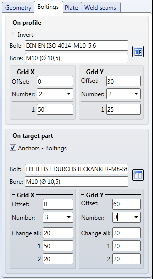
The Boltings tab
For both boltings of the variant (i.e. On profile and On target part) you can specify in the areas Grid X and Grid Y (X- and Y-direction of the grid in top view of the bores), an Offset (distance of the centroid of the profile) and the Number of bores for each direction.
In the input field below you can assign the distances between the bores either individually (the corresponding number of input fields will be displayed for the previously selected number of bores), or, in case of identical distances, use the Change all field to set all bores at once.
Click the  icon to open the catalogue for the selection of the individual bolting elements.
If you activate the Invert checkbox in the On profile area, the bolting will be inserted in the opposite direction.
In the On target part area, the Anchors - Boltings checkbox is activated by default. If you deactivate the checkbox, the bolting will be conversion into a bolting without anchor. The Invert option will then become visible here, too.
On the Plate tab you can click the icon to load a sheet or plate type for each plate of the variant from the catalogue (e.g. a wide flat steel).
On the Weld seams tab you can specify whether weld seams should be inserted or not (in the latter case deactivate the Insertcheckbox), and enter the thickness of weld seams in the corresponding Weld seam thickness input field.
![]() Please note:
Please note:


Connections / Design Variants (ME)
|
© Copyright 1994-2019, ISD Software und Systeme GmbH |